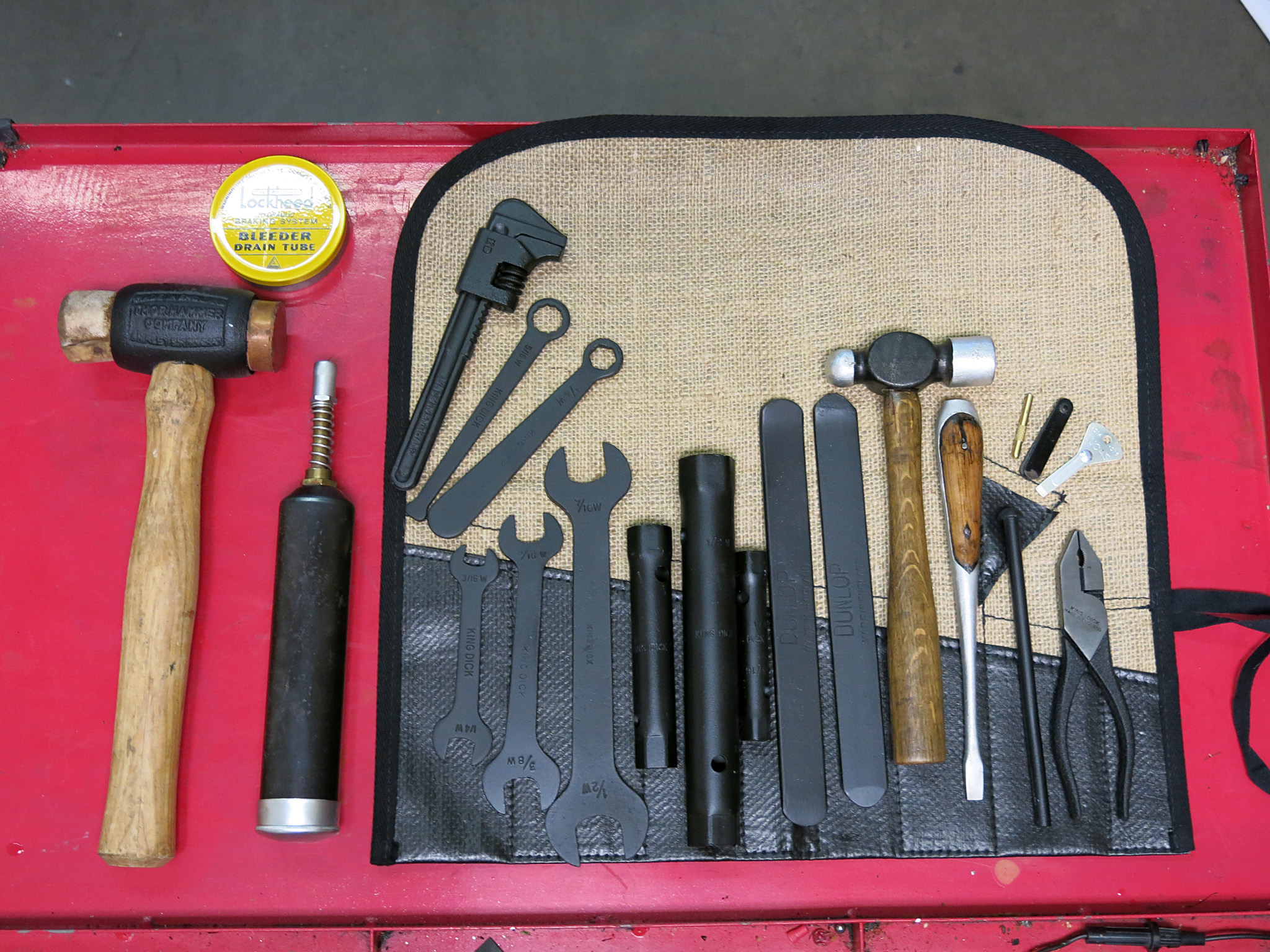
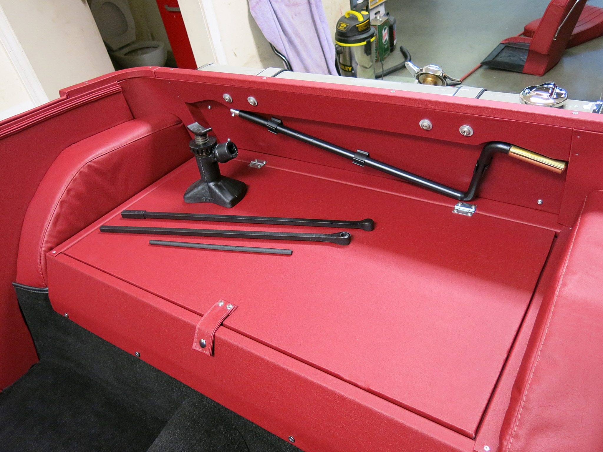
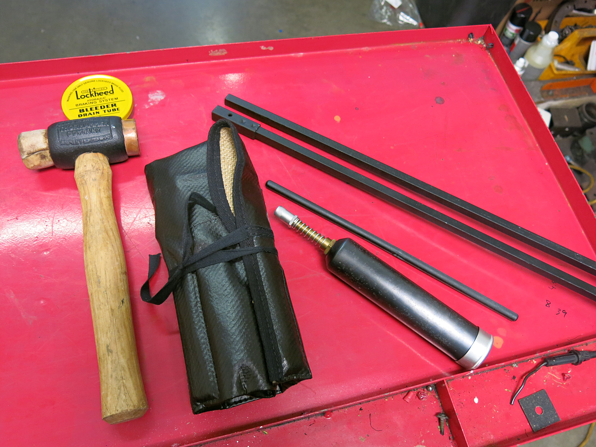
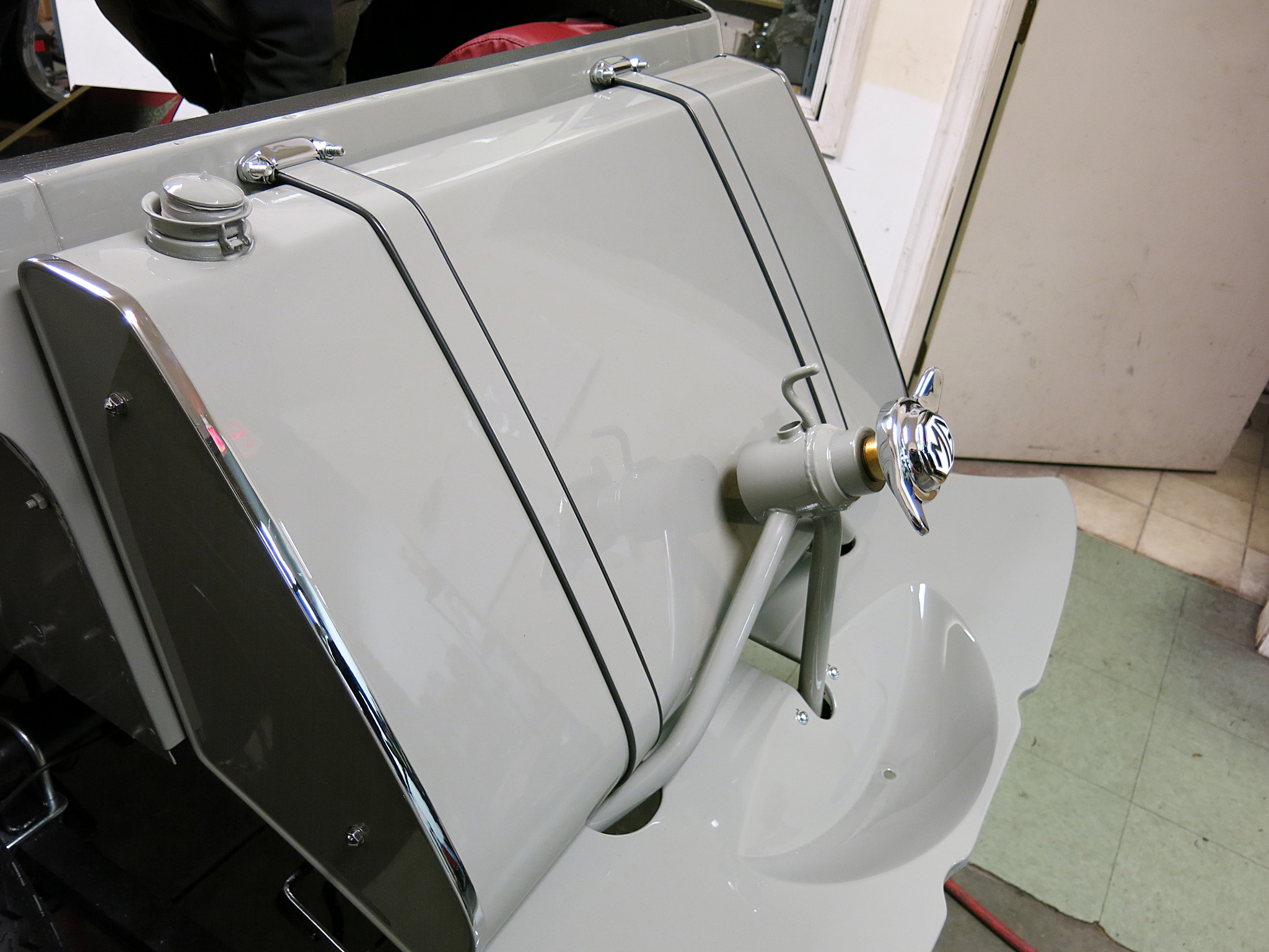
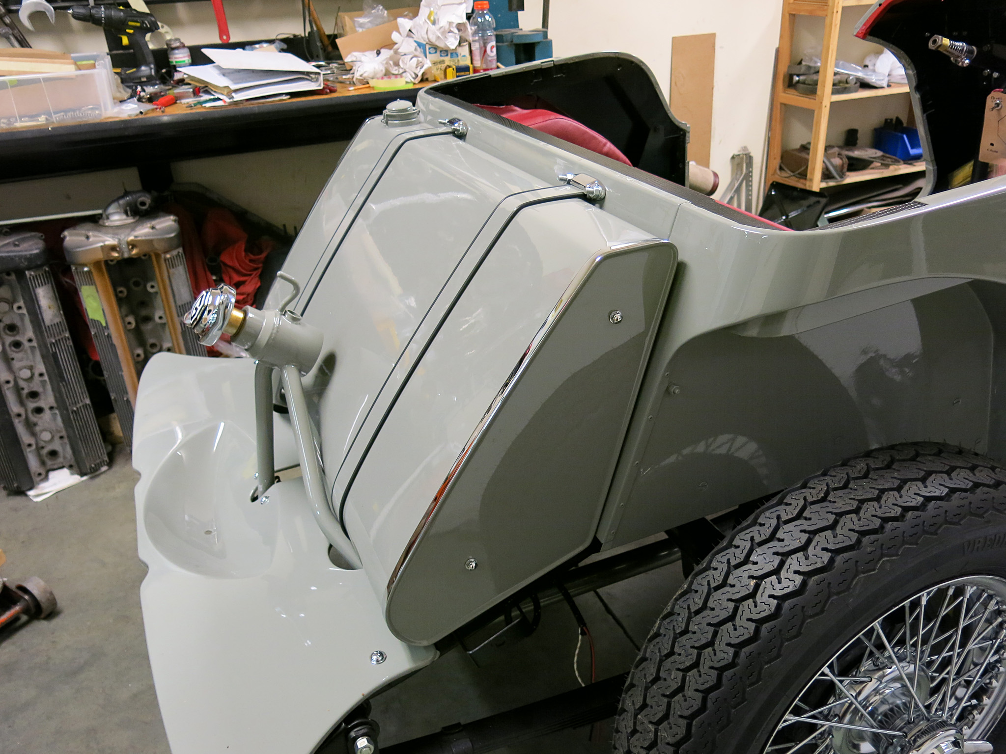
Today we assembled the Tools for our 1954 MG TF restoration project. Many of these tuck into the ammunition box that is welded into the front firewall except the starting crank that is fastened to the rear bodywork.
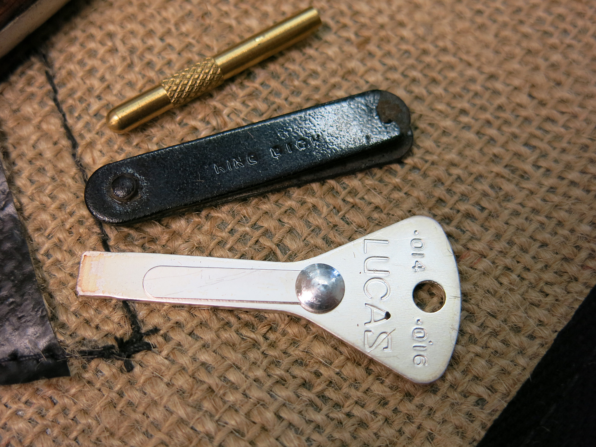
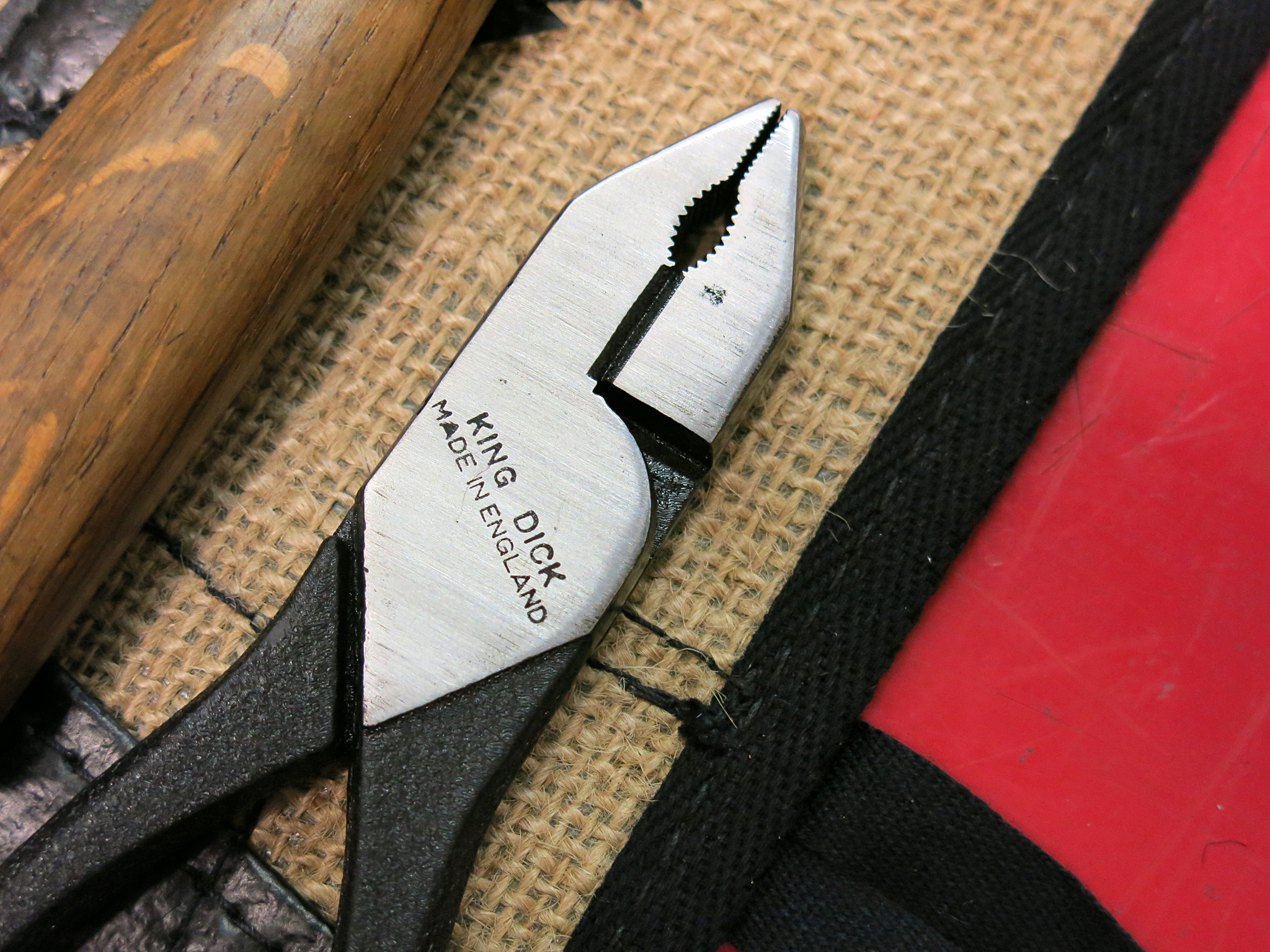
Subtle details include an Enots grease gun with a Black Oxide/Blued barrel and the correct King Dick pliers with new wrinkle finish.
It took many talents to bring this kit together including a new roll from the The In-Point PTY Limited who manufacture a replica bag with the correct latex covered hessian/jute material.
A few of the items are original to the car and came in the ammunition box including 2 of the open spanners and all the box-spanners. Many of the scarcer items cam from Hugh Pite including the rare king dick feeler gauge, a short-handle ball peen hammer and an original King Dick jack with handle!
According the very excellent Original MGTF Midget website our kit is now very complete:
King Dick Ring-Type tappet spanner
King Dick Ring Spanner for cylinder head nuts
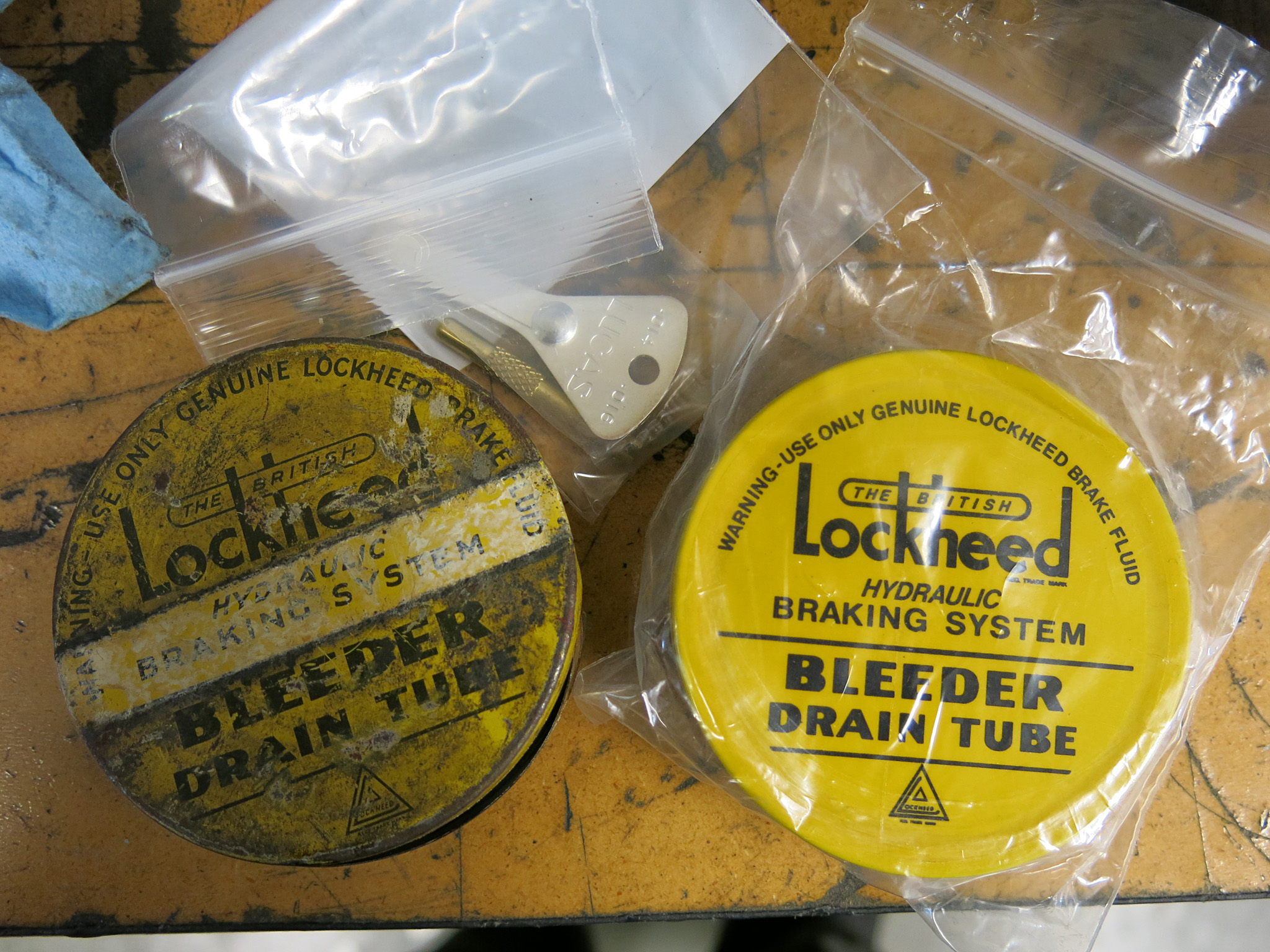
King Dick .019 Tappet Feeler Gauge
¾-pound ball peen hammer
King Dick Pliers
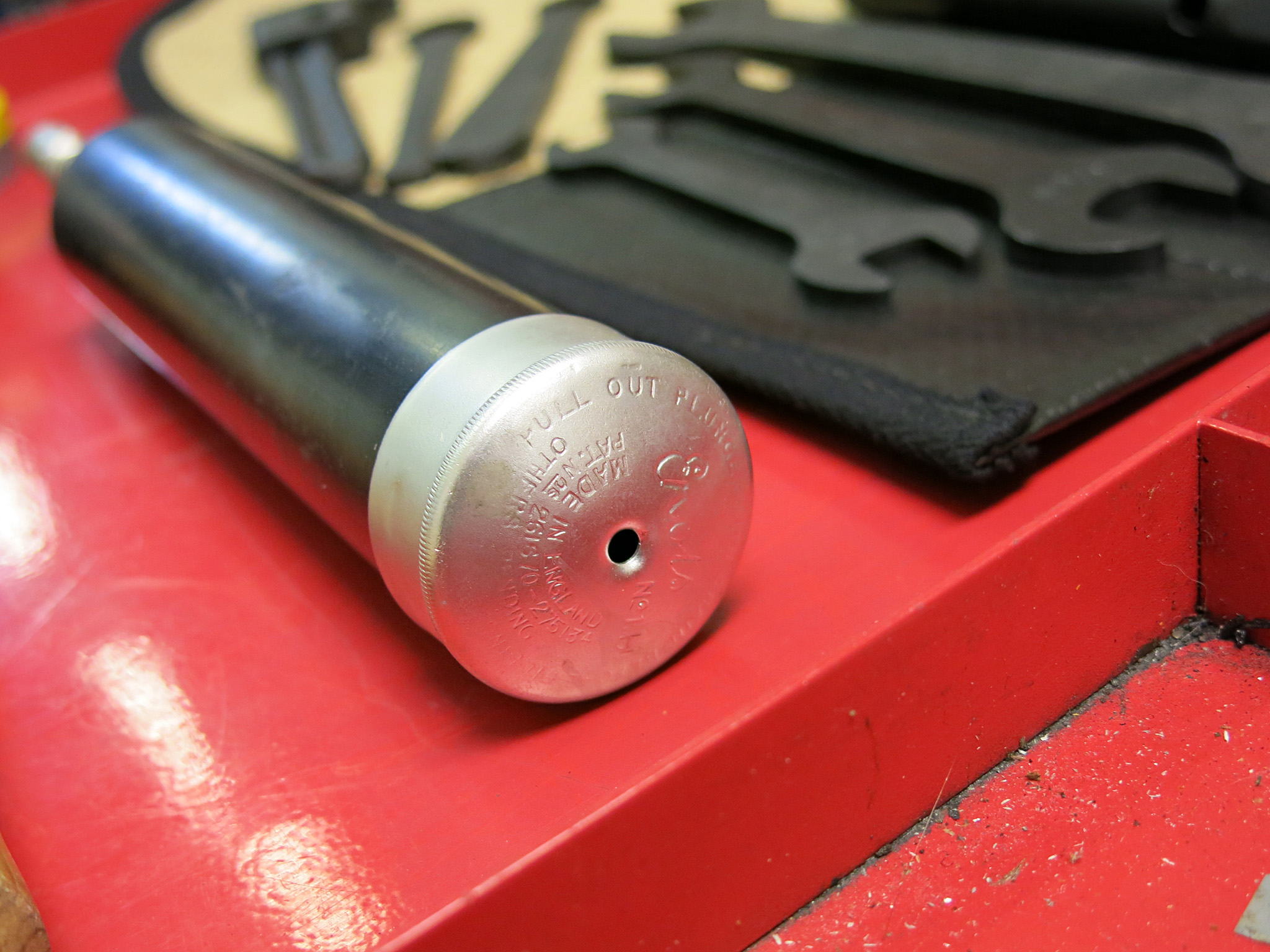
ENOTS No.1 Grease Gun
Two Dunlop Tire Levers
Tire Valve Spanner
Lucas Distributor Feeler and screwdriver
Screwdriver
Unlabelled Shelly-Type Tyre Pump
King Dick Set of Box Spanners
King Dick Set of Open Spanners
King Dick Adjustable spanner
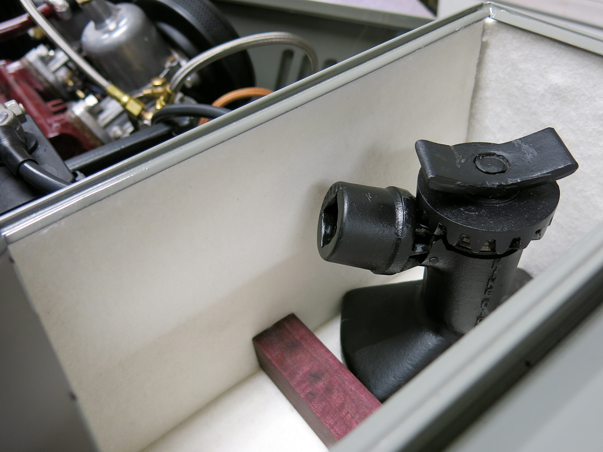
King Dick 1077 Jack
King Dick Jack Handles
6-Inch Tommy Bar
THOR knock-off hammer
Here is the King Dick 1077 Jack sitting in its new home, the ammunition box fitted with white felt.
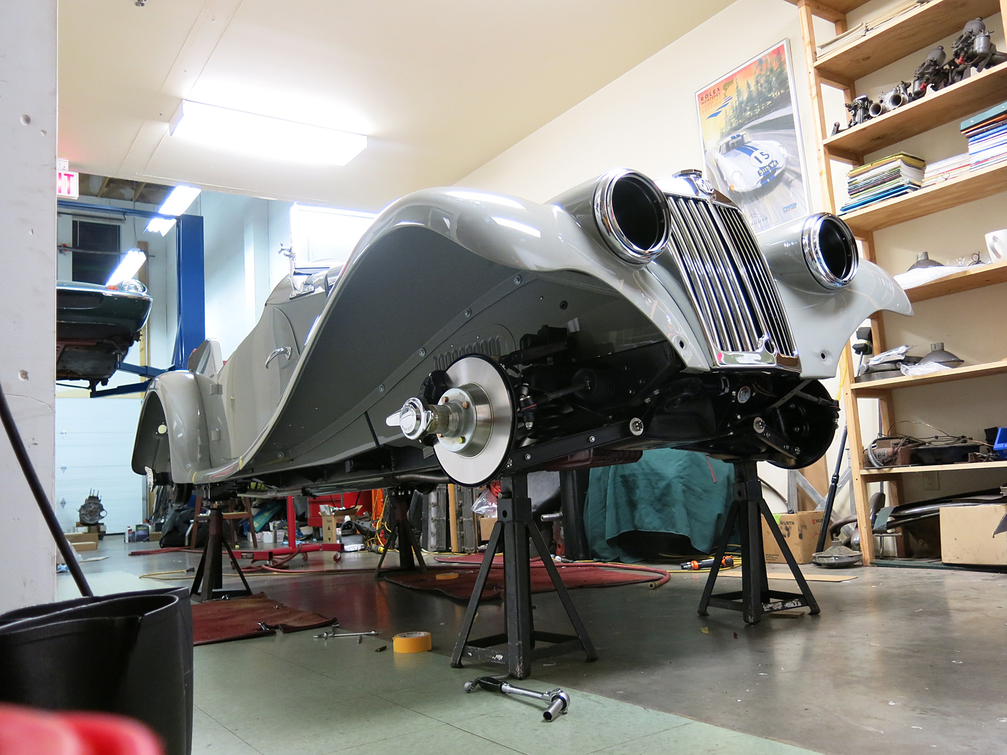
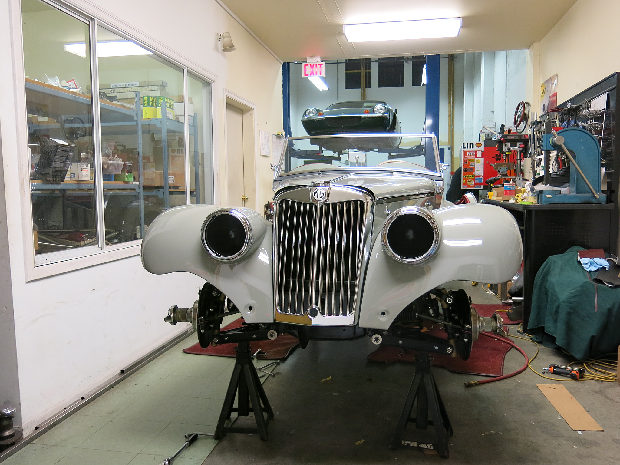
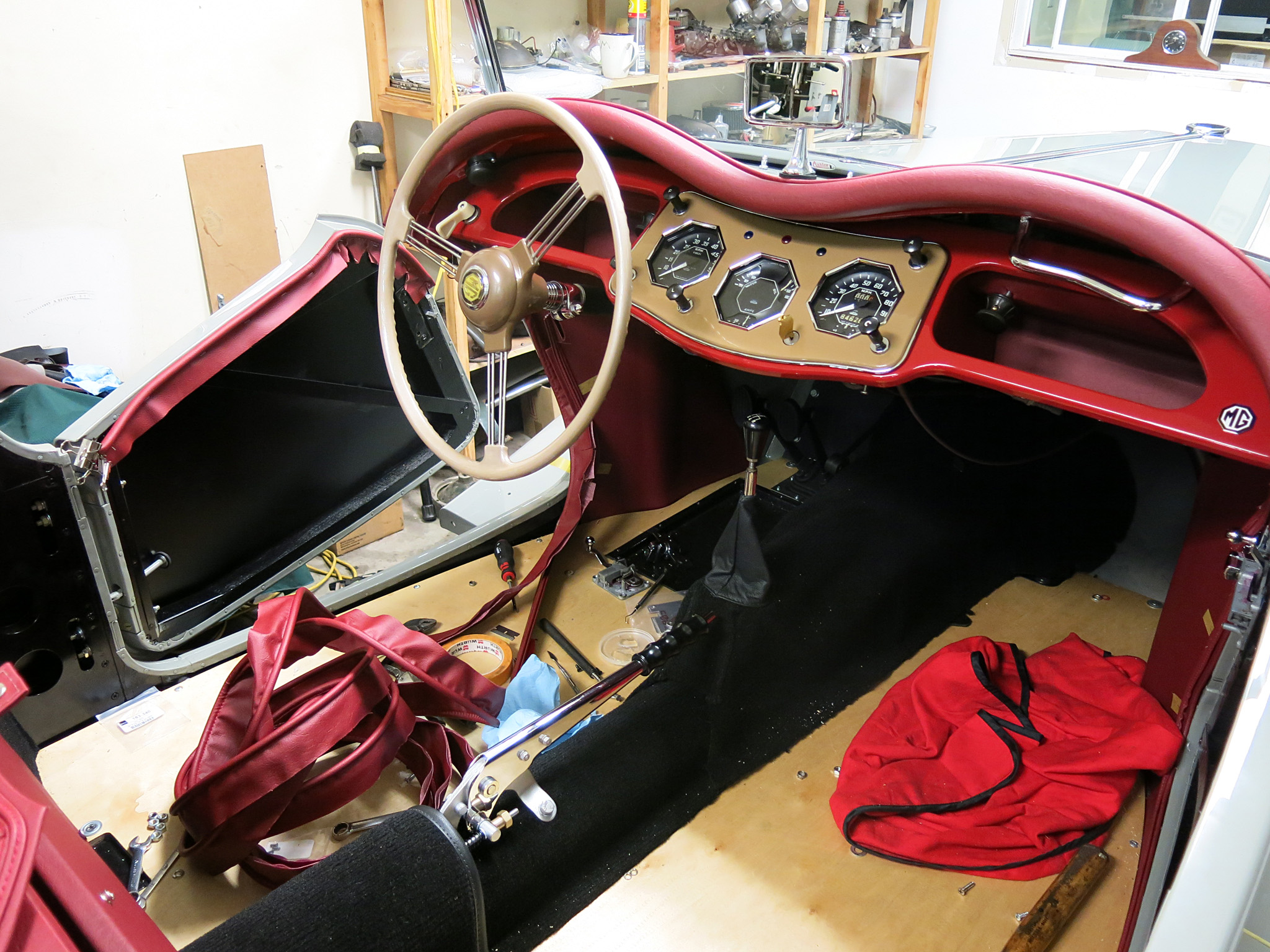
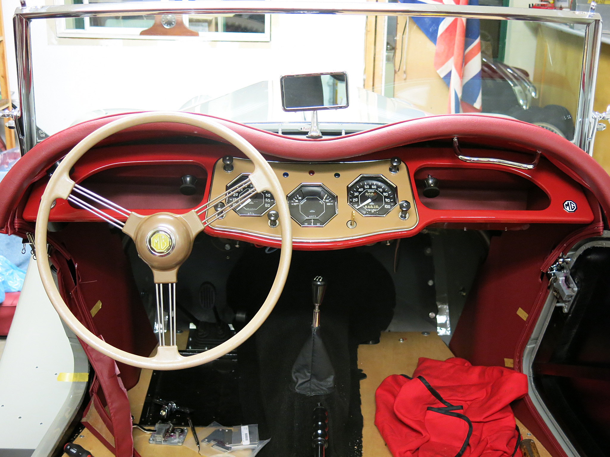
I think this is the last post before our MG TF is completely complete.
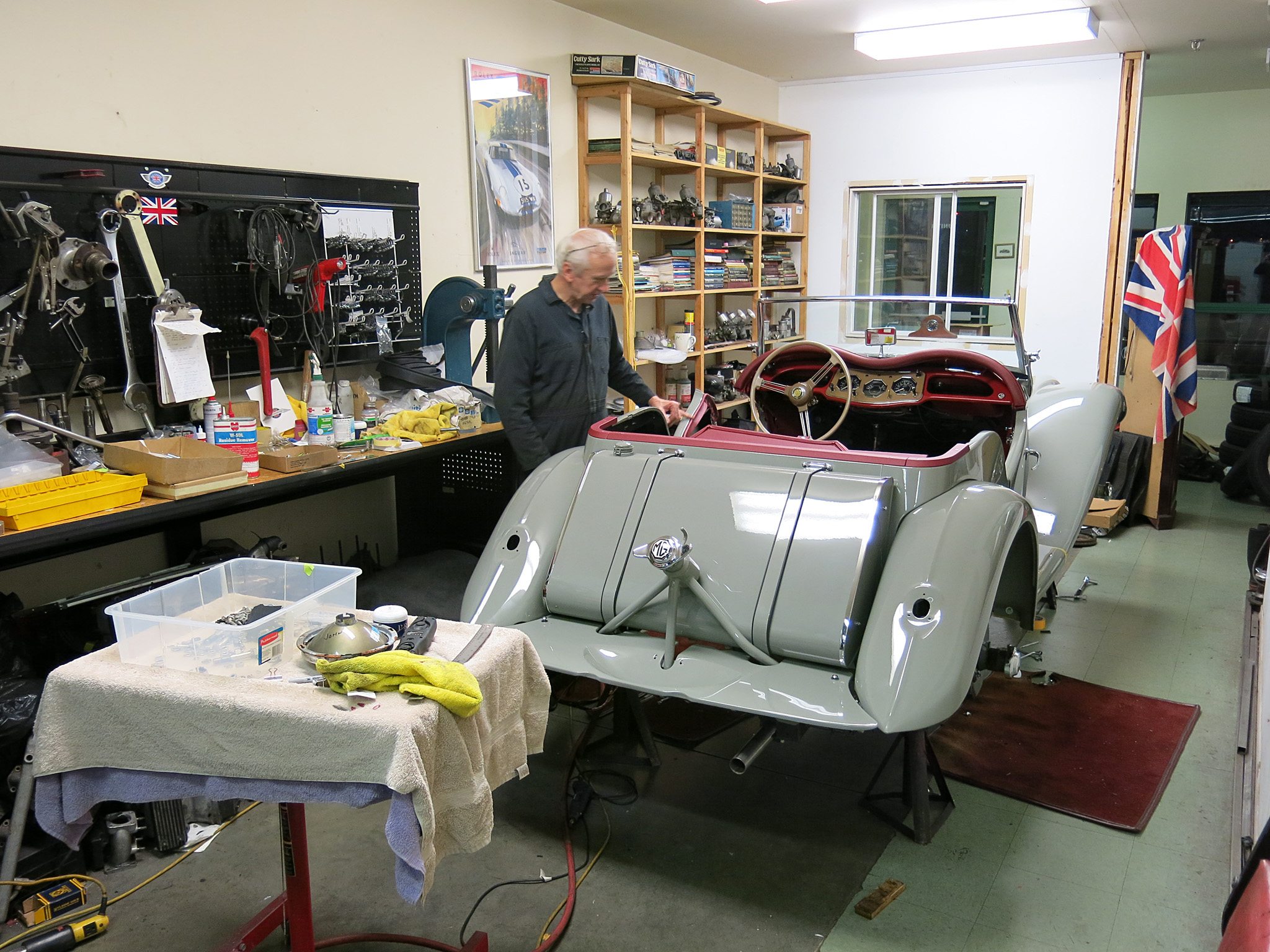
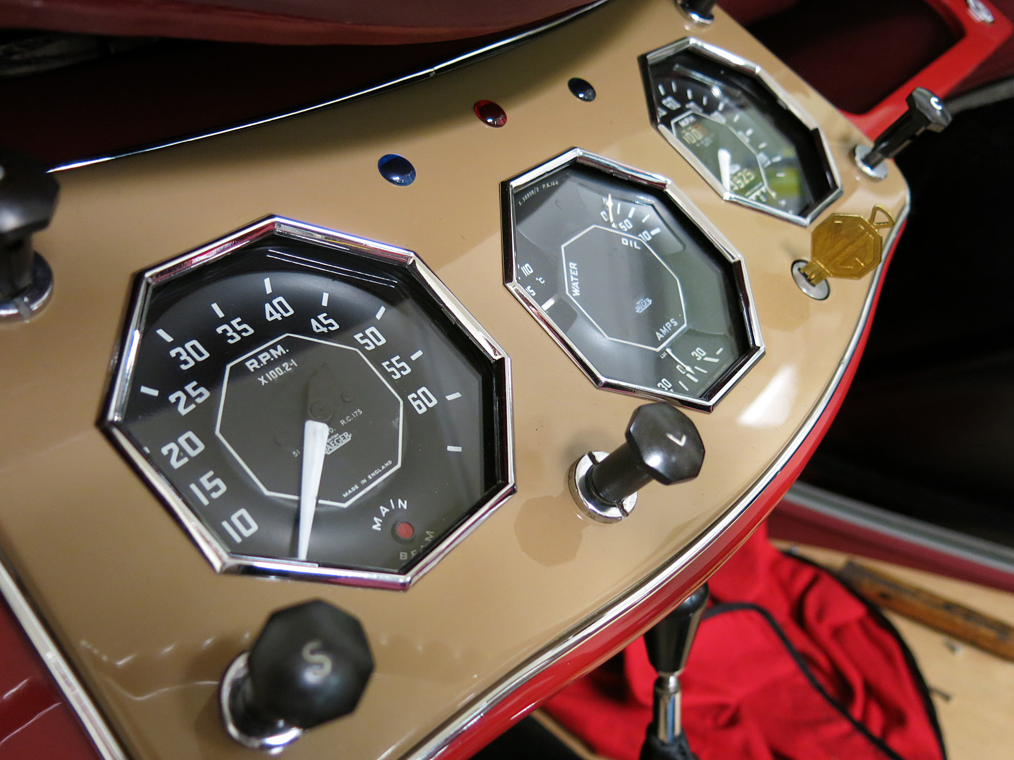
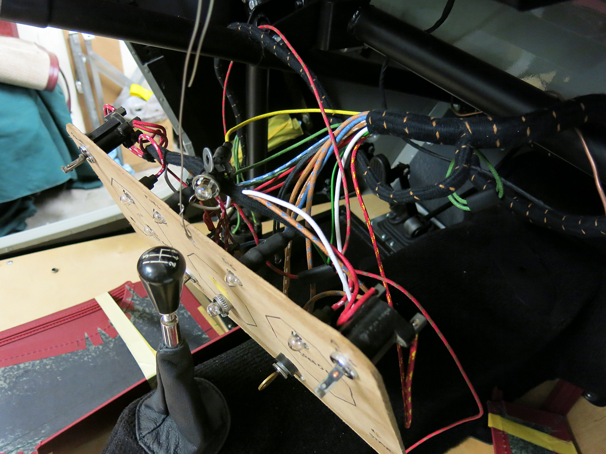
Fitted is the dashboard painted with the original colors found behind the dash with a lovely wheel by Ben Corsten/
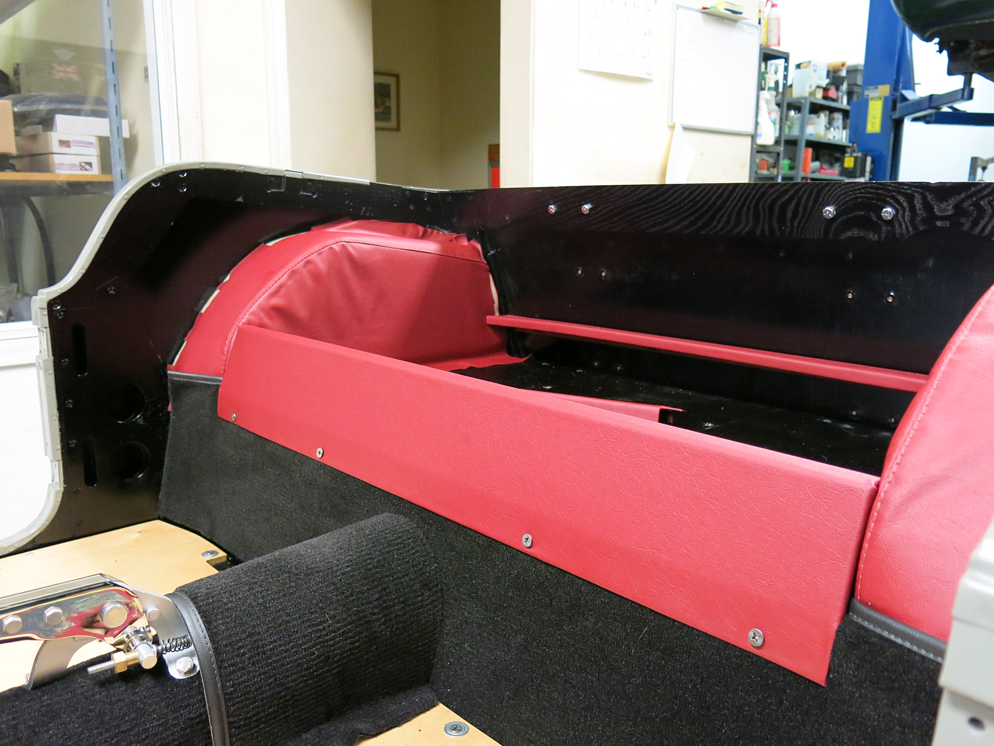
The amount of upholstery work is tremendous for such a small car, so you’ll have to excuse us for more unlabelled photos. Much work has to be done for a Christmas delivery yet!
This is a step-by-step instruction on assembling the E-Type subframes, suspension, steering rack, sway bar, control arms, uprights and lots of brackets/spacers/loop clips which need to be installed at these steps. The installation of the engine subframes is a crucial step in the assembly of the E-Type, and requires careful attention to detail to ensure proper alignment and function.
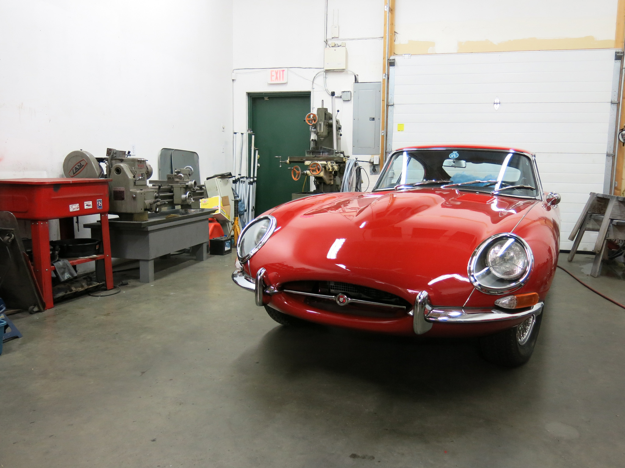
1965 Jaguar E-Type Series I at Owen Automotive
Please read through the steps in their entirety before proceeding.
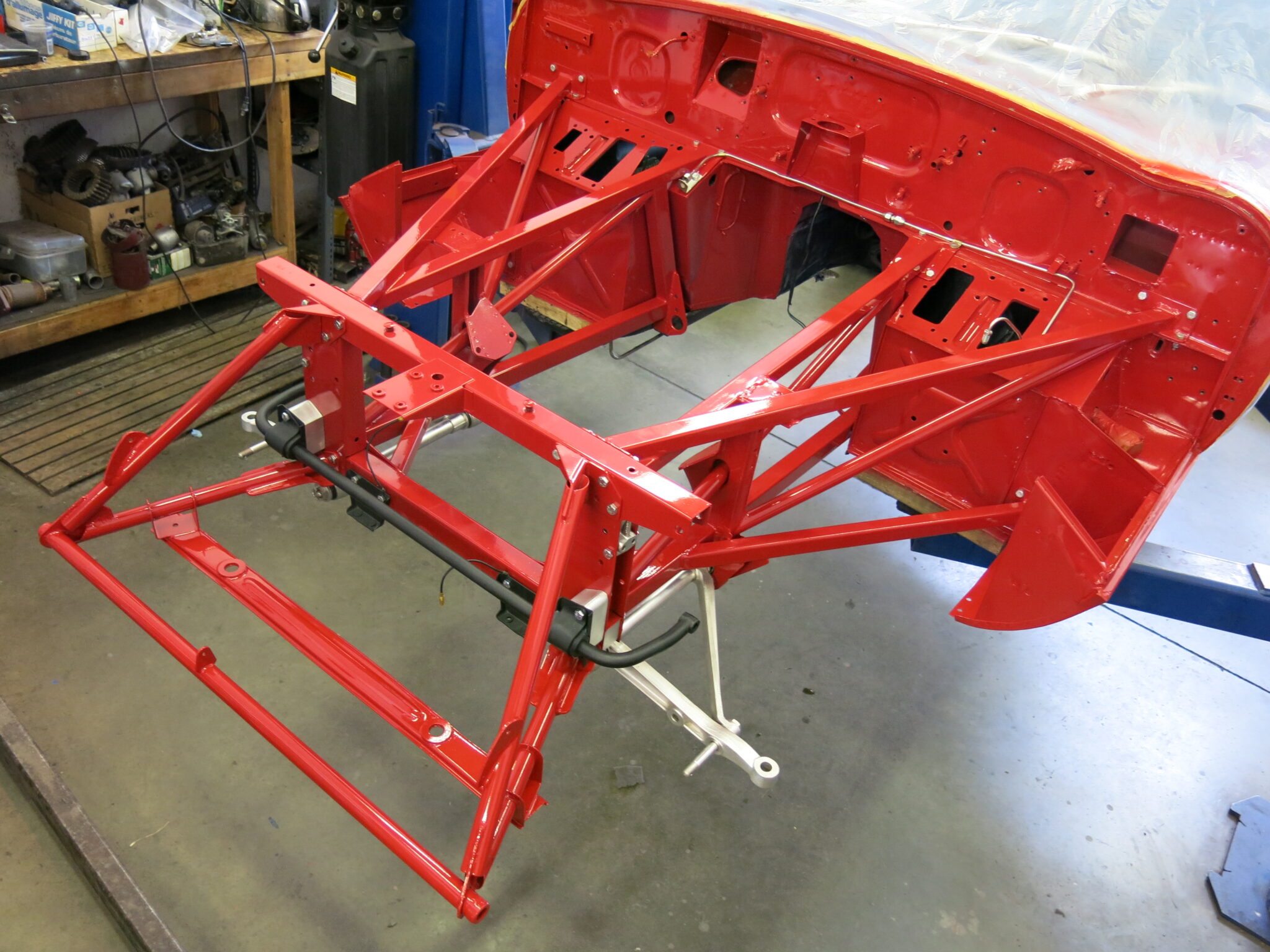
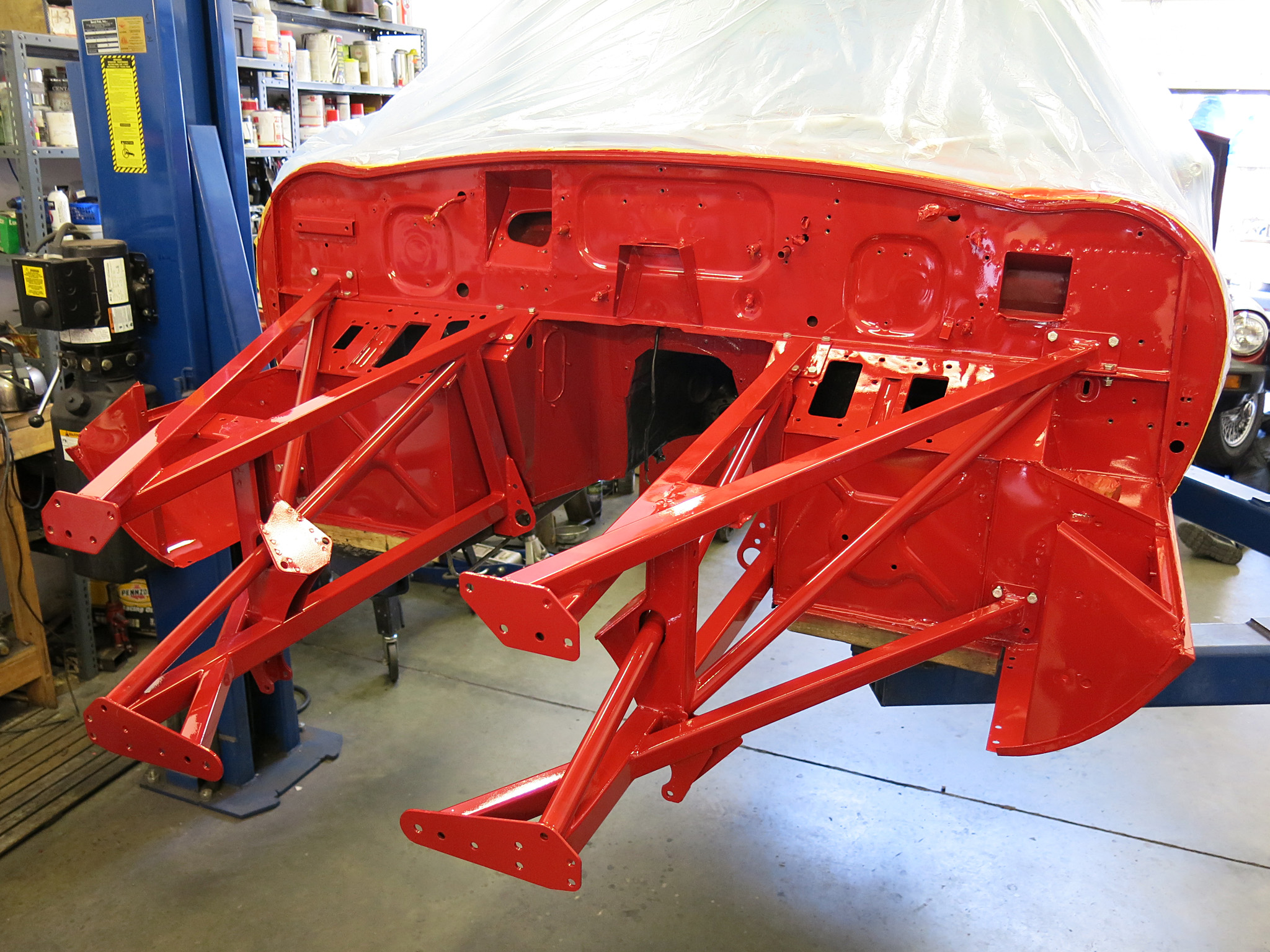
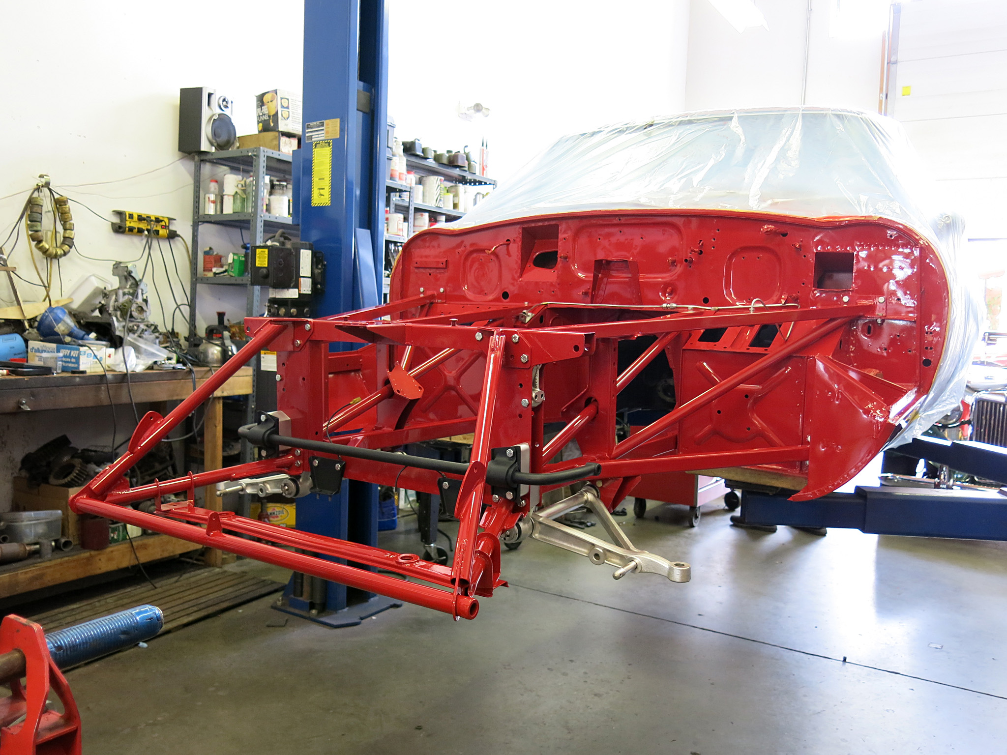
The Engine Frame Assembly of the Jaguar E-Type are constructed from bronze-welded Reynolds 531 tubes which rigid mounted to firewall of the car. Reynolds 531 is used for both the right and left frames (C15030, C15029) and Picture Frame Assembly C28922. They are known for their strength and durability, however, these tubes can suffer from cracks and internal corrosion over time.
One of the most common areas to find cracks on the engine subframe is on the lower engine frame tube where the engine mount is located. This area is subjected to a significant amount of stress and movement from the engine which can cause fatigue and eventually lead to cracking. In addition, surface corrosion can also be found underneath the brake fluid reservoirs. This is a result of exposure to DOT4 brake fluid that compromises the paint.
To prevent these issues, it is recommended to apply cavity protection spray inside the engine subframes before assembly.
If the car shows any signs of needing steel panel replacement in the body monocoque of a Jaguar E-Type, then the subframes must also be replaced. This is because the subframes and the body monocoque are closely interconnected structural components that work together to provide the vehicle with its overall strength and rigidity.
There are many aftermarket sources for the right and left engine sub frames of a Jaguar E-Type, including some with upgrade options that include thicker 14 SWG steel stock and Martin Robey lists their top version Uprated Engine Side Frames for Jaguar E-Type MRE93RHU / MRE94LHU built with T45 Carbon Manganese Steel. These updated units have an additional gusset bronze welded between the formed engine mounting post.
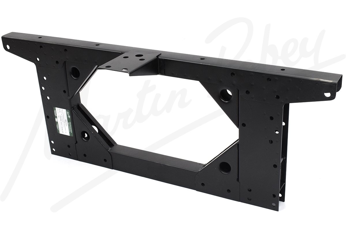
Martin Robey’s MRE92U Uprated ‘Stage 2’ Picture Frame Crossmember with additional gussets and filets
The Picture Frame Assembly C15014 C25368 is a structural component of the Jaguar E-Type subframes that is sandwiched between the engine subframe and bonnet subframes. It is a mild-steel pressed unit that uses fulcrum blocks to prevent crushing of the structure and serve double duty as suspension mounting points.
Like the subframes, the Picture frame is also available in updated form Martin Robey with gussets and fillets which are round tubes welded between the trailing and leading edge that where not part of the original design.
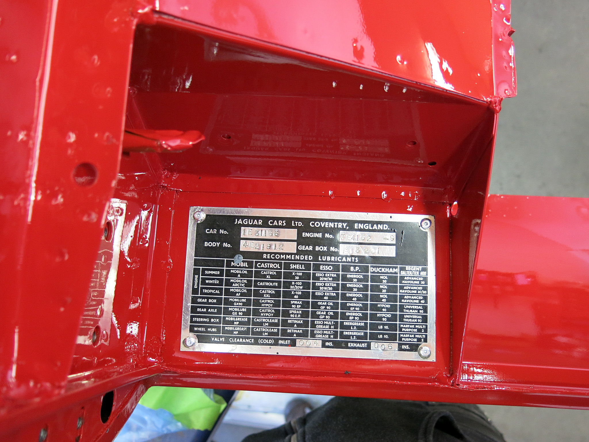
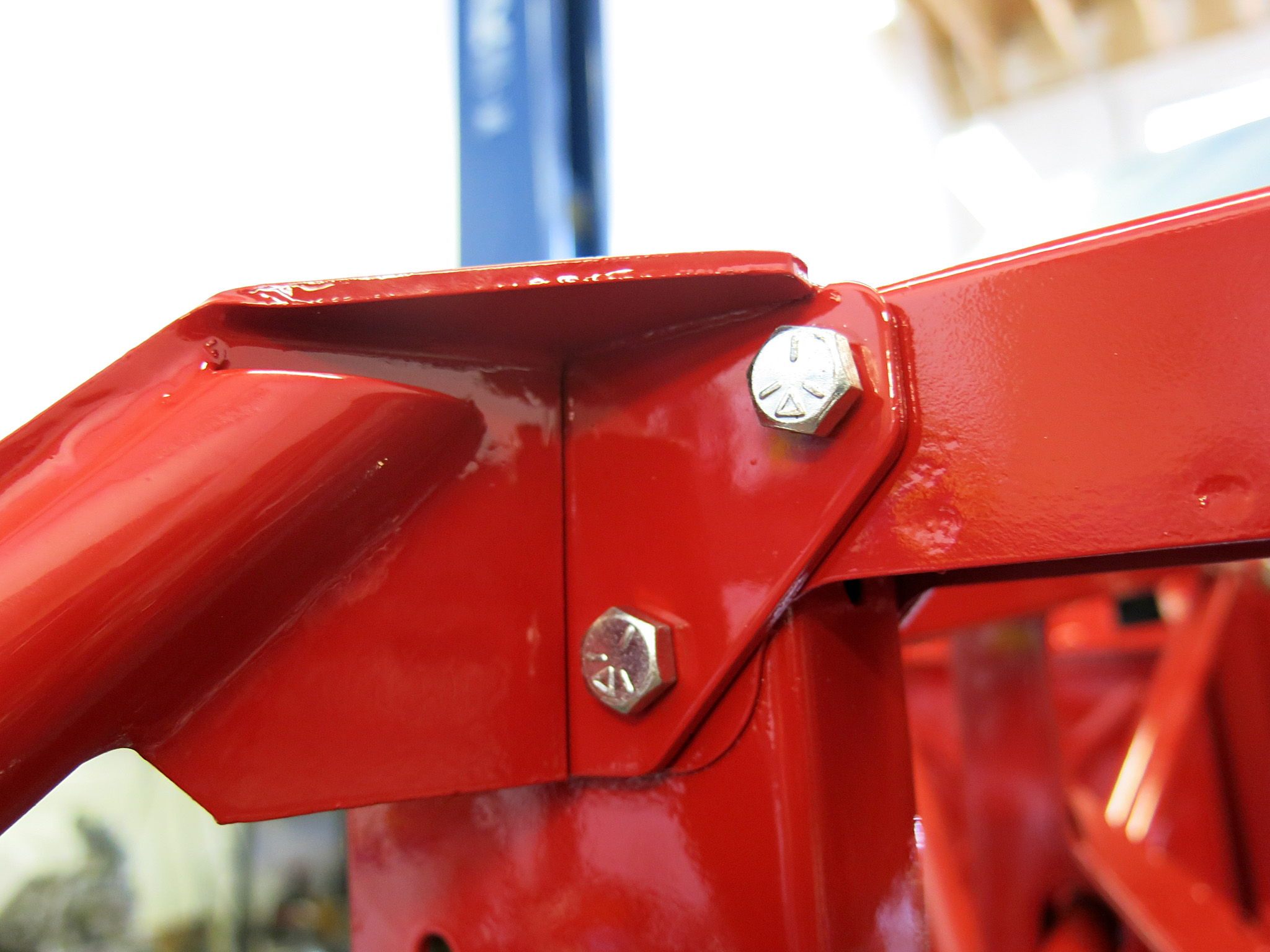
When made at the factory the picture frames were first painted then later stamped with the chassis number on the right-hand side near the telescopic shock absorber. This process would have caused some damage to the paint and this is often seen as a sign of an original picture frame stamping.
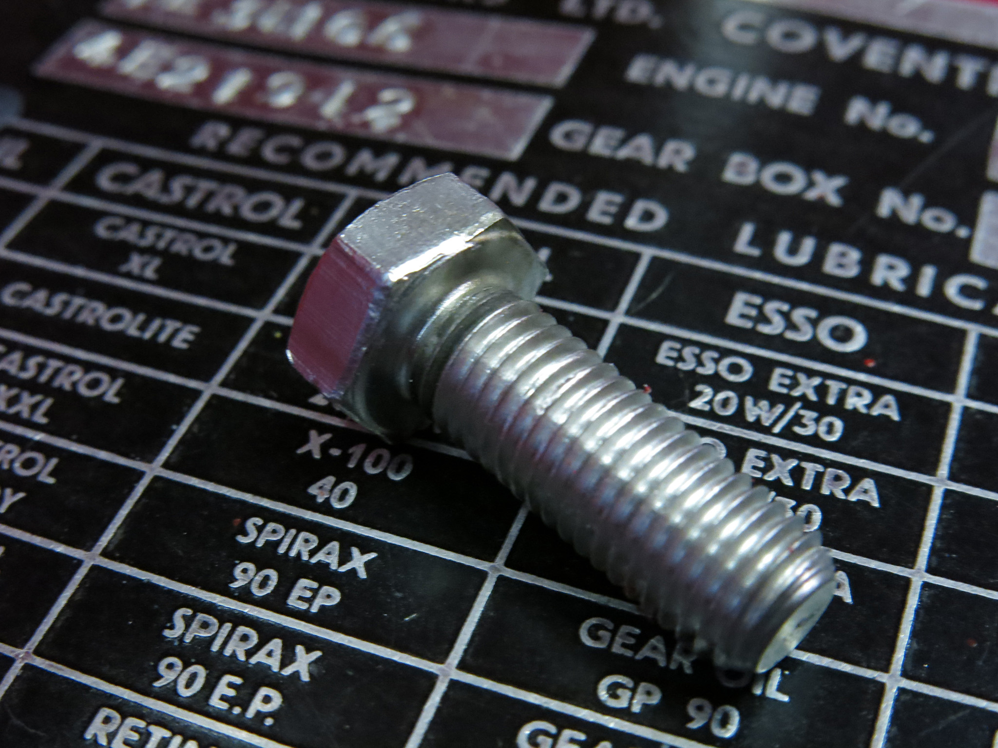
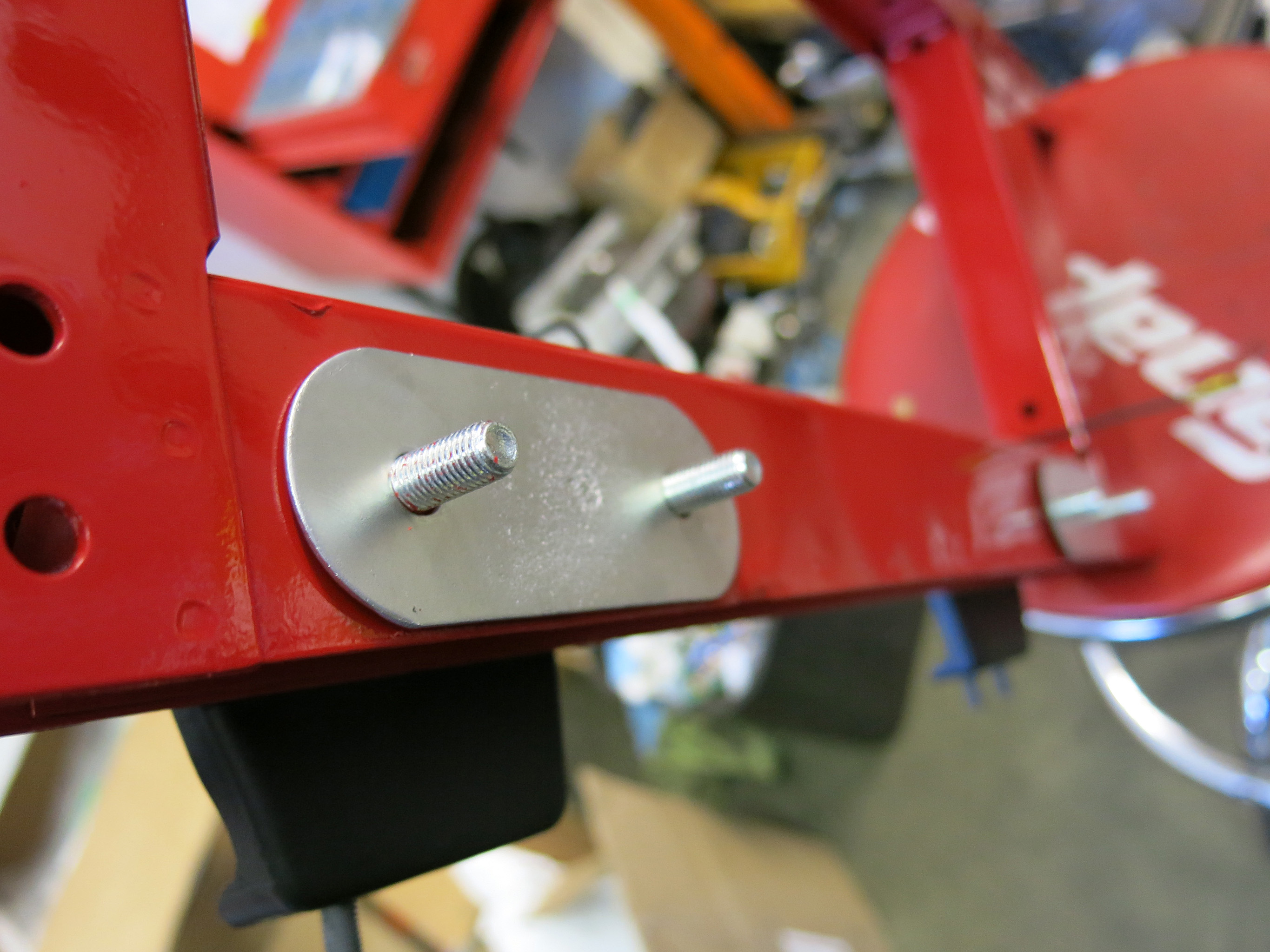
The picture frame uses many 2-4 inch-long 5/16-24 GKN bolts and these are available as a set.They are retained by long skirt 5/16-24 nyloc nuts plated in silver cadmium. Large circular punches can aid in locating the bolt holes when installing the picture frame.
Almost all the subframe hardware on Series I Jaguar E-Type cars is electroplated with silver cadmium, which provides a durable and corrosion-resistant surface. As production passed, Jaguar increasingly used gold cadmium plating for the Series II which was mainly limited to the bolts.
The first 13 steps will be all mounted with loose bolts, until the entire subframe assembly is built and then tightened as a complete unit.
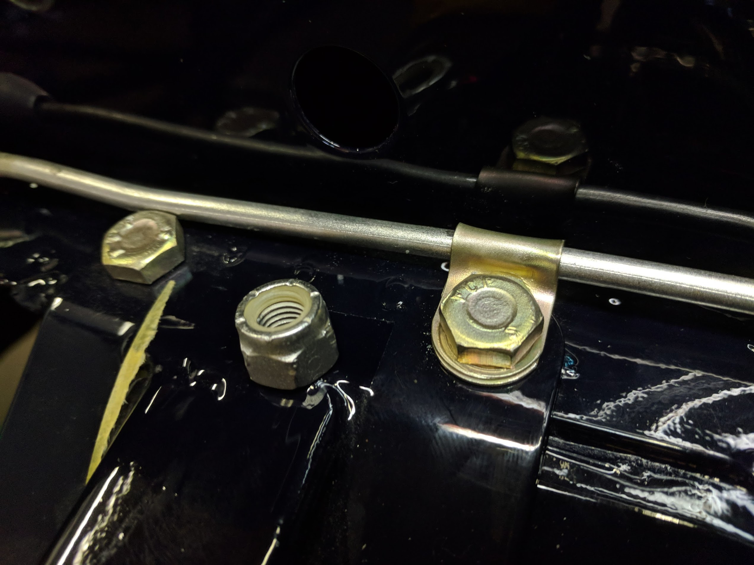
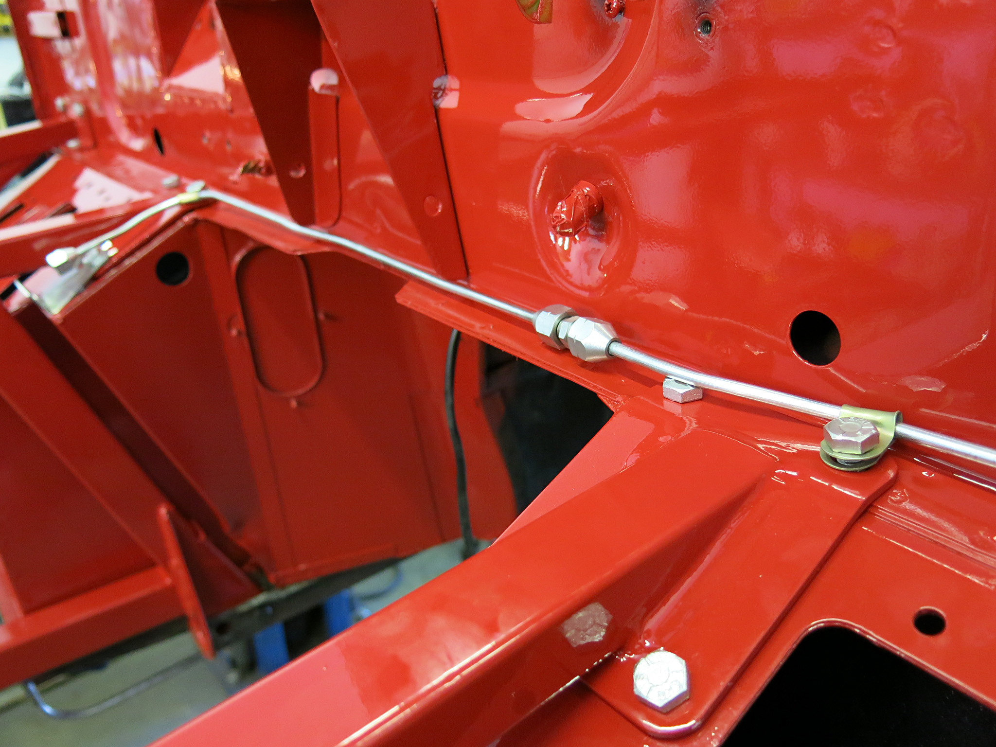
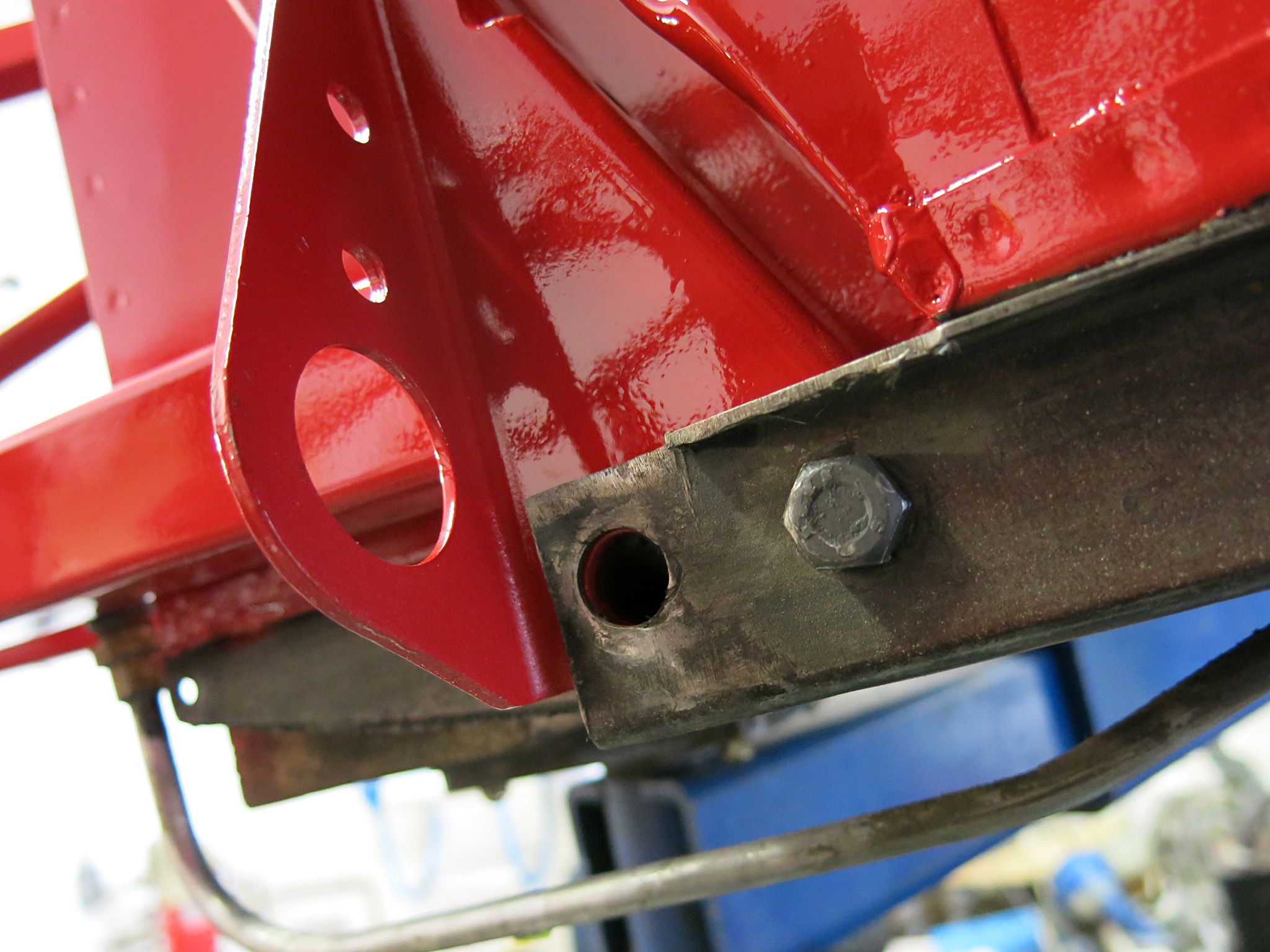
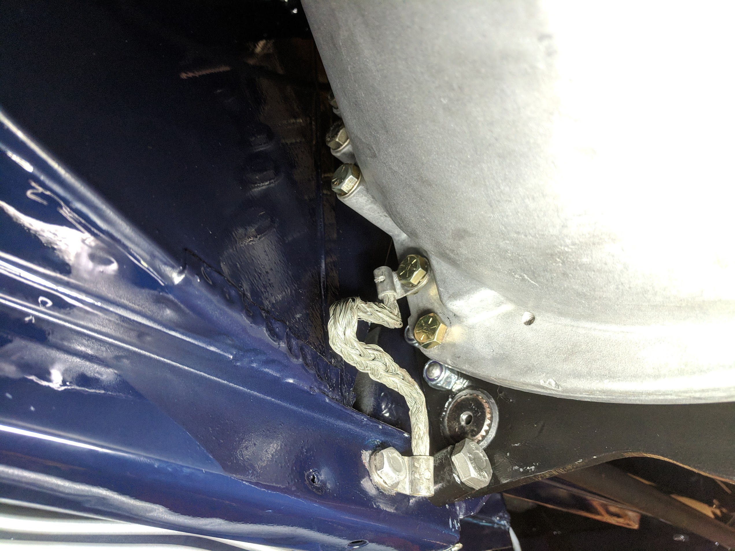
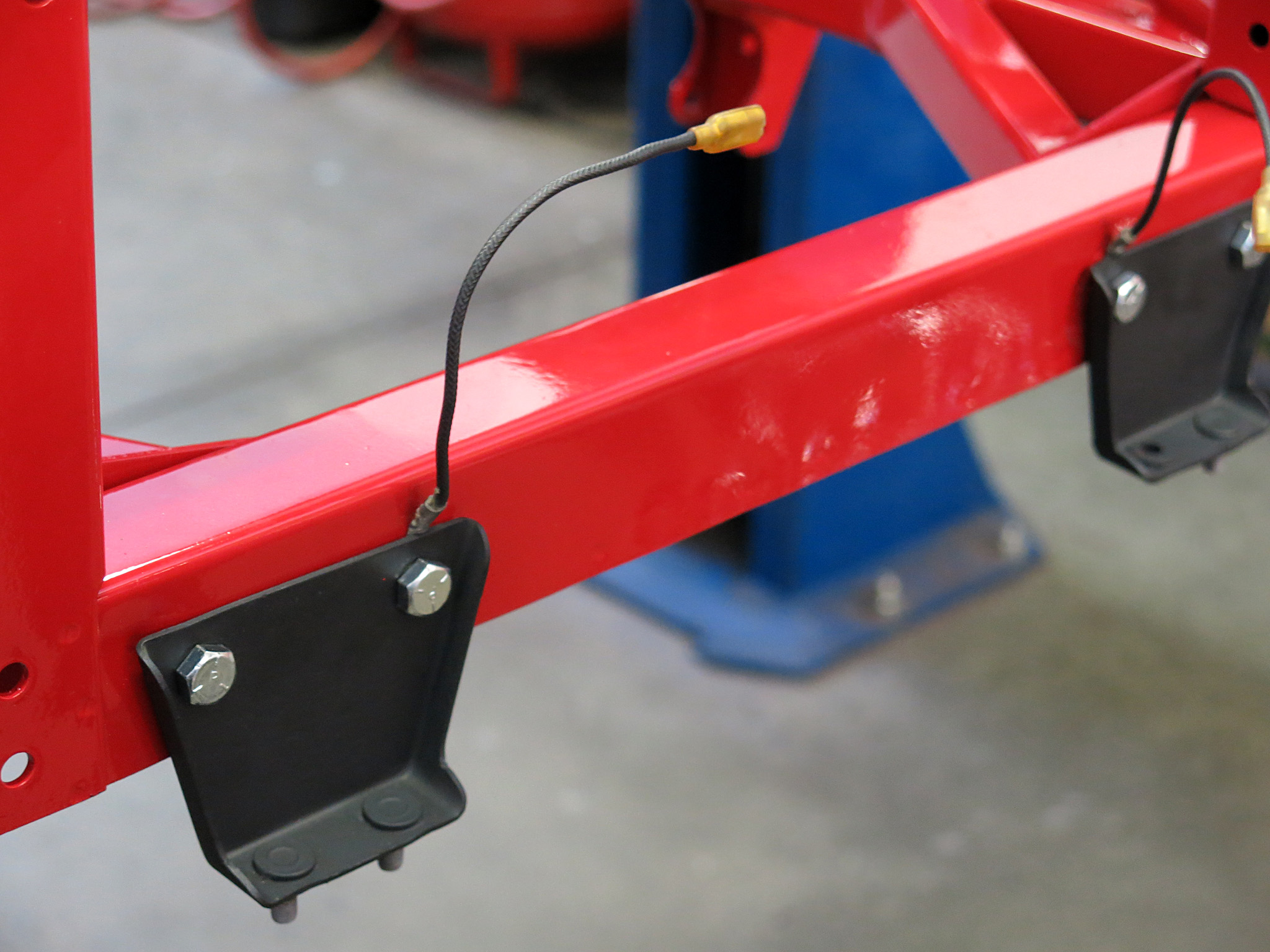
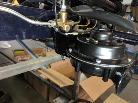
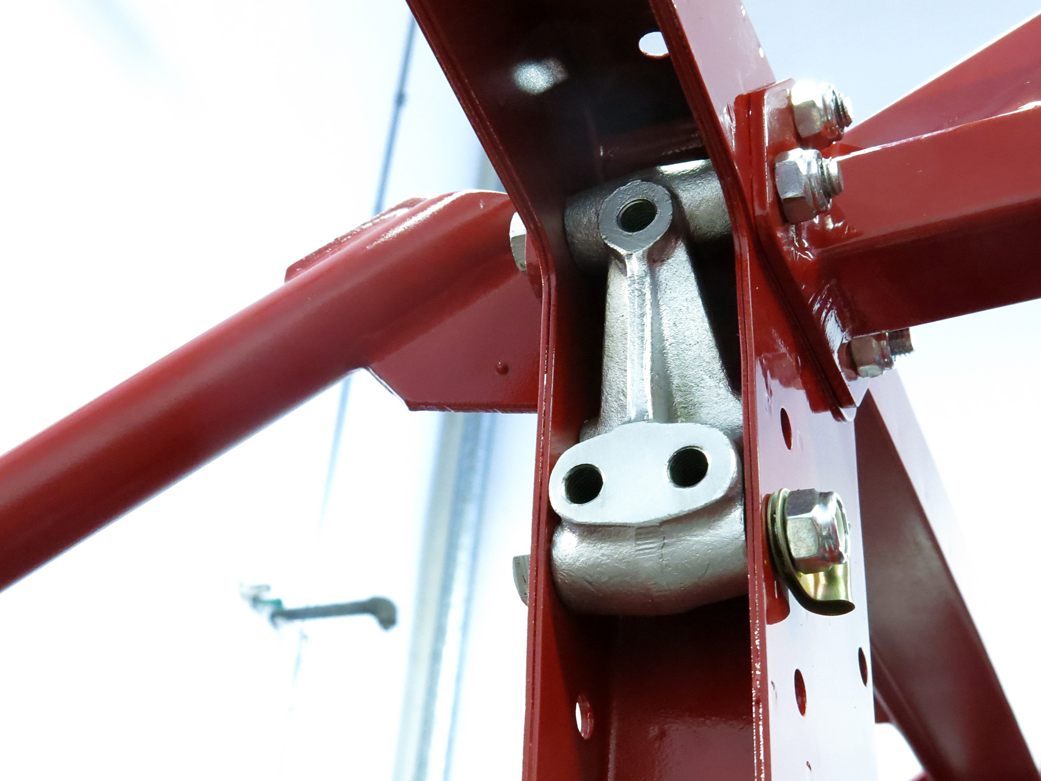
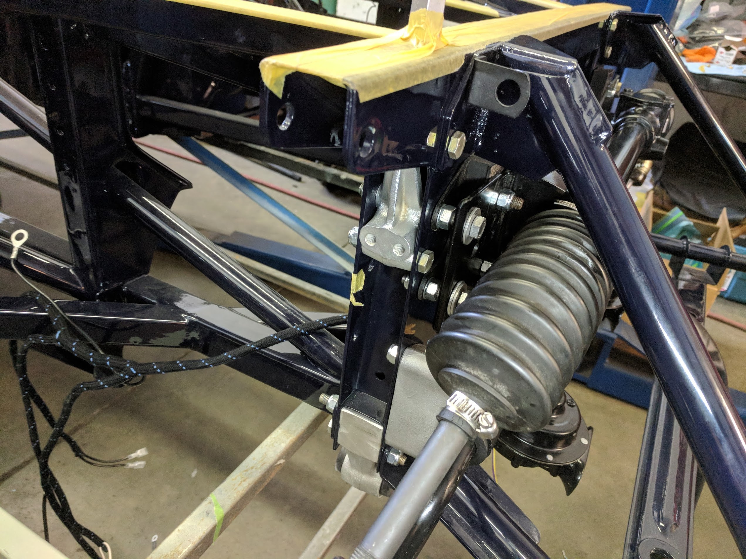
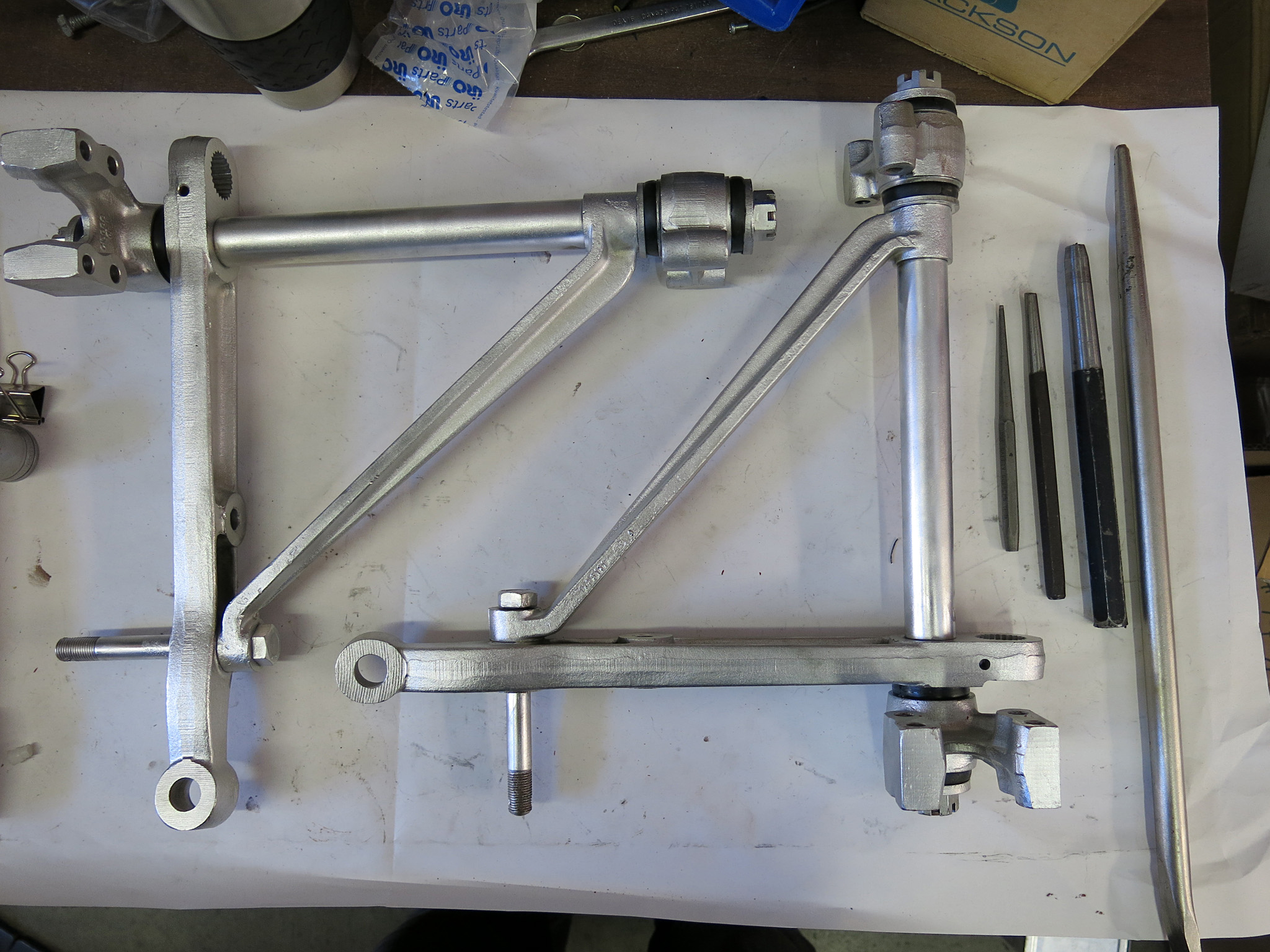
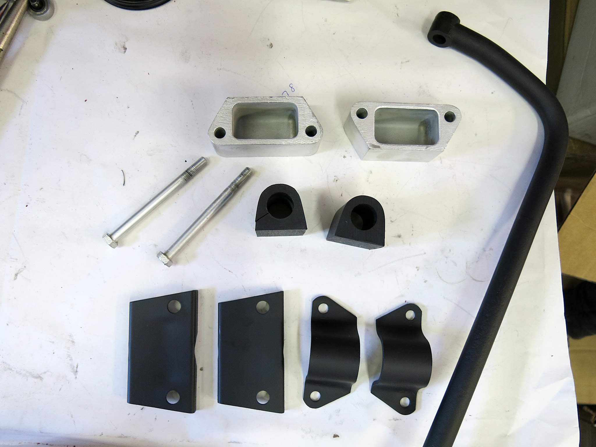
STEP 1 – The first step is to reattach the serial number plate to the firewall with 1/8-inch aluminum rivets. This is what an exceptional 1967 original appears like. It is common to see drips of paint on surface as the factory used touchup paint in several points of the engine bay.STEP2- Locate the 5/16-24×1 GKN subframe bolts, 24 in all. These bolts were installed by Jaguar without washers or lockwashers, fear not for your paint as the bolt has a raised edge that does not scratch the paint when tightened. Some people locktite the original units while others replace with grade 5 or grade 7 bolts with typical washers and lock washers. Later S2 cars FCF 5/16×1 bolts in gold cadmium plate.As a note later Series II cars used FCF bolts of the same size but with gold cad otherwise known as Olive Drab. Next to these is an original nyloc nut as used on the picture frames.STEP 3 – Next we will consider loosely attaching the main engine subframes just finger tight with the provided 5/16×1 bolts, but not until checking the notes below regarding the brake line loops and fuel filter bracket location. If the threads are painted on the firewall a 5/16-24 tap or thread cleaner would be necessary.STEP3 NOTE – The loop clamps for the brake line should be in the following spots and the brake line L-braket will also need to be fitted. This 1965 model had gold-CAD loops. All bolts are just sitting there with the nylocs nuts barely on.STEP 4 : The lower 3/8×2¼ bolt should be loosely installed through the floor channel, but the larger ½x3½ bolt will go on with the reaction plate.The LH engine subframe also mounts the engine ground strap. Here is an original unit fitted in place.STEP 5 – Install the E-Type front cross member aka the ‘Picture Frame’ with the lower 4 5/16×2¼bolts. These Frame Shims C15045 sit between the picture frame and engine subframes. If your car is a 4.2 the horn brackets will also go through these four bolts.STEP 5 NOTE – The horns on a 4.2 liter car are located on the Picture frame as well as the horn ground wires which can benefit from bare-metal contact between the surfaces. Earlier cars had the larger horns built into the hood.Series II cars locate the brake distribution block on the LH horn bracket.STEP 6 – The upper control arm fulcrum block can be loosely installed. Leave the middle hole for the steering rack mount and the bottom hole on both sides will later have a loop clamp for the wiring harness. 5/16×2 just barely clear modern 5/16 lock washers.STEP 7 – Loosely attach the two 5/16×2½ bolts through the three subframes on the passenger side.Step 7.5 – Install the same two inner bolts on the driver’s side which also incorporates the 3-way hydraulic union .Series II cars run small L-brackets on the top of the picture frame that must be installed at this time for the radiator supports.STEP 8 – Assemble the lower control arms with new bushings in the fulcrum blocks and pre-load them just finger tight with a socket to get the right spacing to attach to the fulcrum blocks to the sub-frames. The lock nuts will be fully tightened later on after the engine is in the car. I have seen later cars which have “L” Left and “R” Right stampings for these pieces. On a 100% original car the fulcrum blocks are positioned with the part number towards the front of the car. Also these bushings only use outter washers that are thicker than normal. Also note there is no washer between the control arm and large fulcrum block.Install the lower control arms with the torsion bars in the correct factory fit. We slid the torsion bar receiving bracket into the middle of the bar, then pushed the torsion bar into the lower control arm and finally pushed the bracket into place.
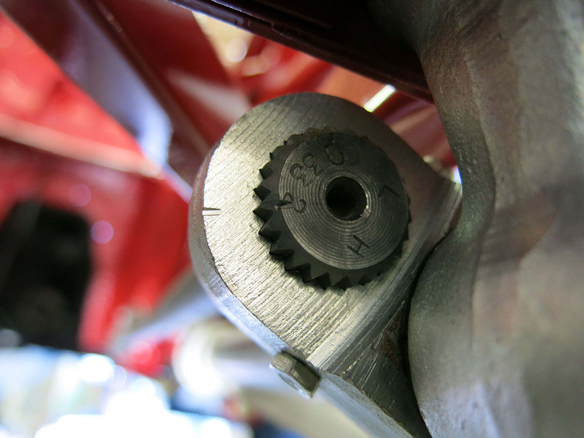
The torsion bars are responsible for maintaining the factory-specified ride height, which is essential for proper suspension geometry and handling performance. When the torsion bars are removed and reinstalled, it is crucial that they are located in the same position as the factory setup to ensure that the ride height and spring rates are correct. If an adjustment needs to be made to the torsion bar suspension on the Jaguar E-Type, it is important to ensure that the left and right bars are correctly located on their respective sides, they are stamped RH and LH respectively on the front leading face. The torsion bars have 24 splines on the front connected to the lower control arm and 25 splines on the rear connected to the reaction plate through a bracket. These splines allow for fine vernier adjustments of the ride-height to be made.
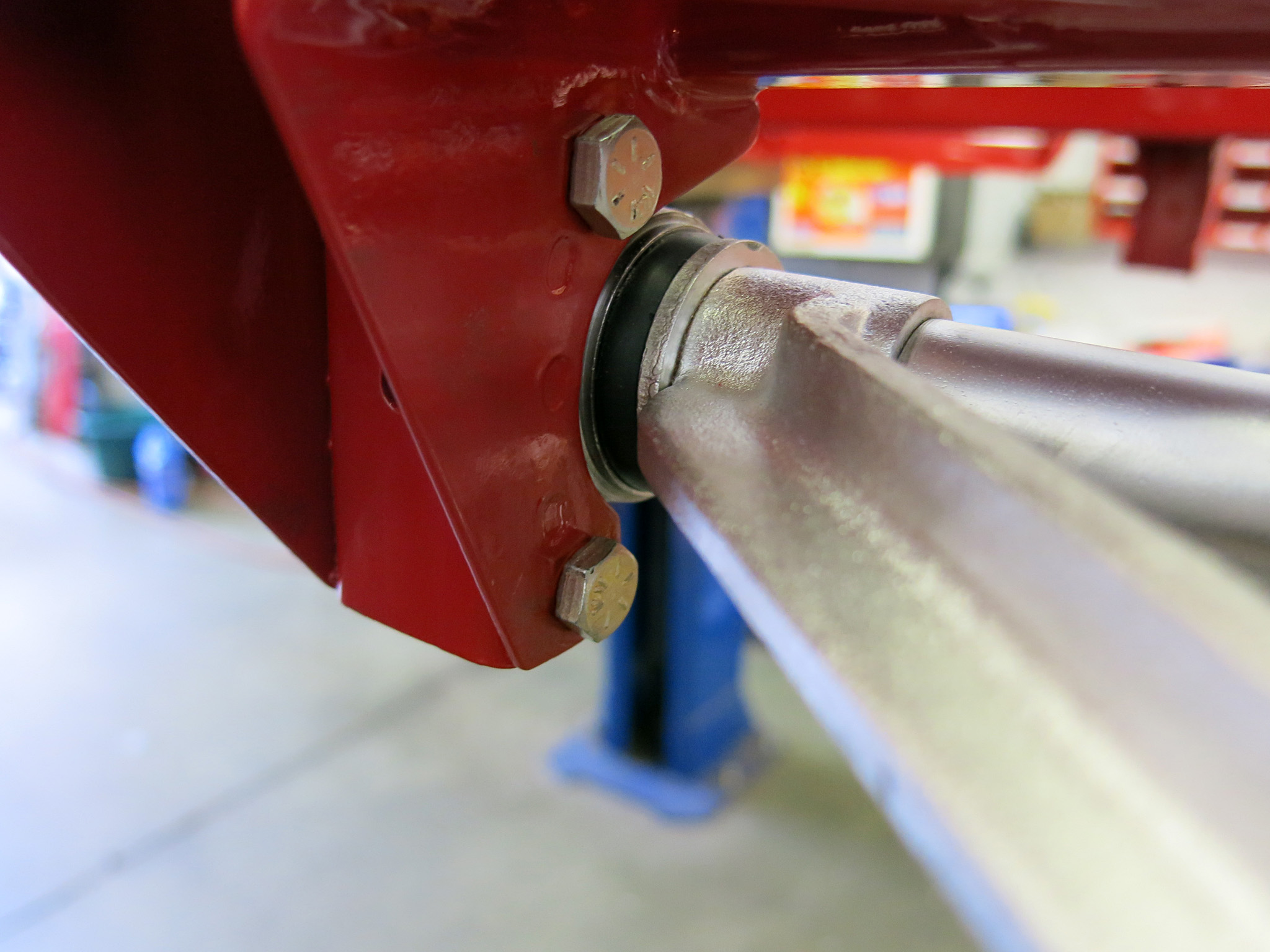
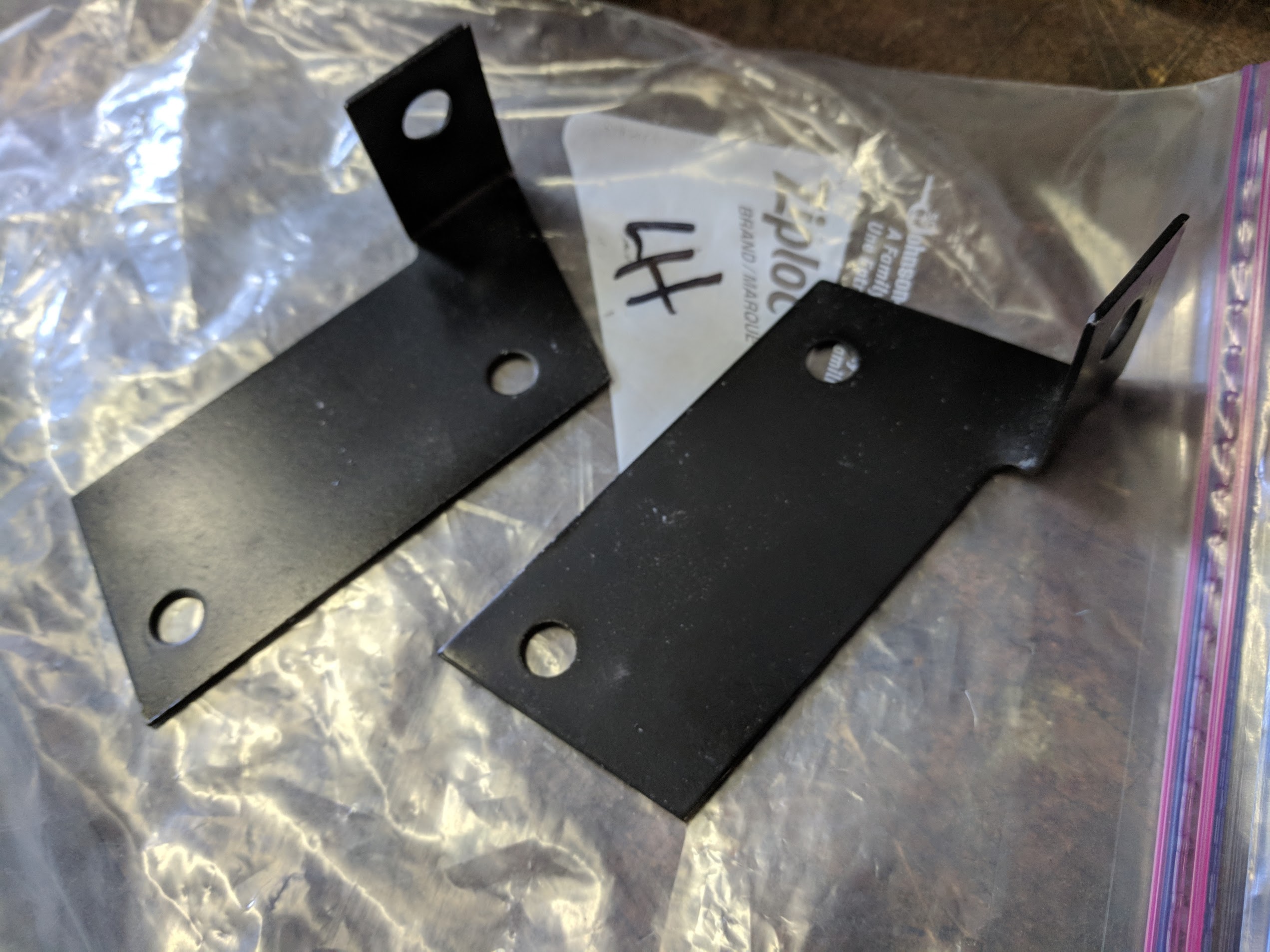
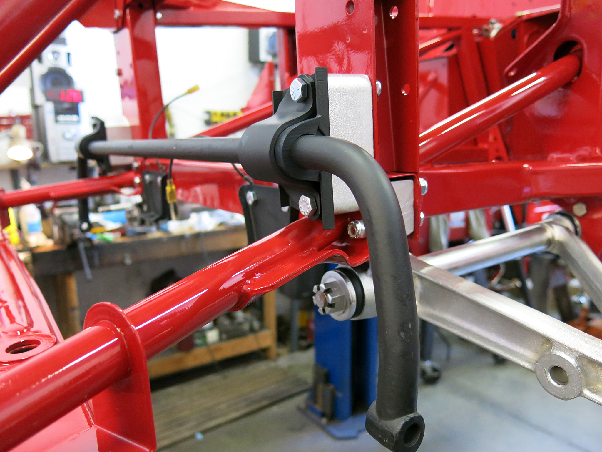
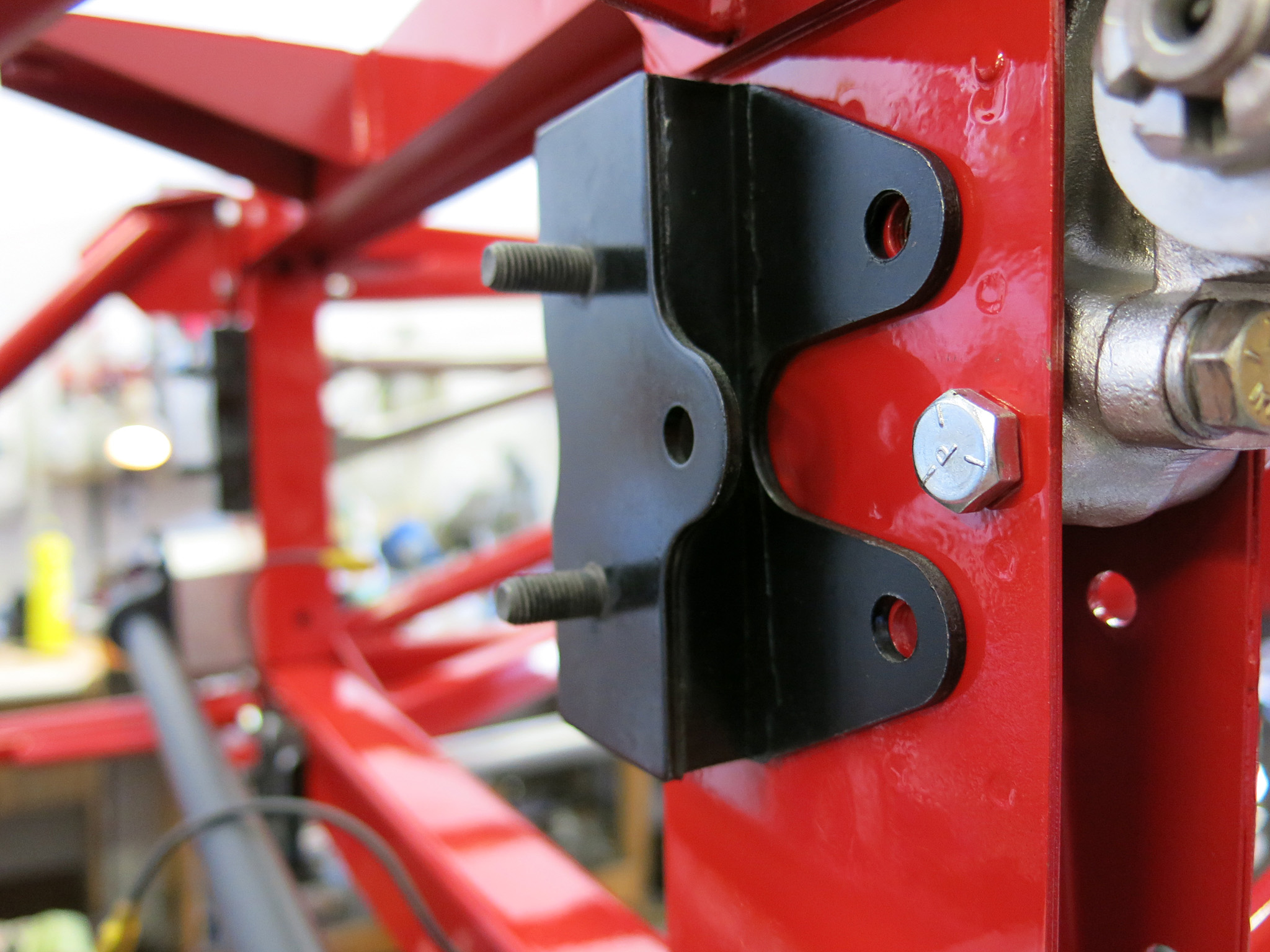
STEP 8 NOTE – We marked the factory original position. You can also make a tool from the service manual that will place the torsion bar correctly. They are stamped LH (Left Hand) and RH (Right Hand) on the front of the bar with an X on the rear. Once the bar is in the exact position the lock bolt can be slid through the control arm. The factory service manual includes a setting link with instructions on how to properly adjust the torsion bars. The recommended method is to install the setting link and rotate the bar until both splines line up exactly and then slip it in. This will ensure that the torsion bars are installed at the correct angle and that the ride height and spring rates are set correctly.We used 2 5/16×2 bolts for the rear lower control arm fulcrum blocks and the must go in from the front for control arm clearance.STEP 10 – All of these sway bar pieces will be needed. The 5/16×4 bolts are specific to this job.Series II cars also have this bracket in the subframe mount to support the brake lines.STEP 12 – Loosely attach the sway bar. Only two bolts hold on the sway bar but they pass through more layers than anything else on the car. Usually a second person is helpful here not to scratch the paint and keep all the pieces intact before the long bolts can be threaded through. Also use silicon or rubber grease in on the sway bar so it can freely pivot in the rubber bushing.
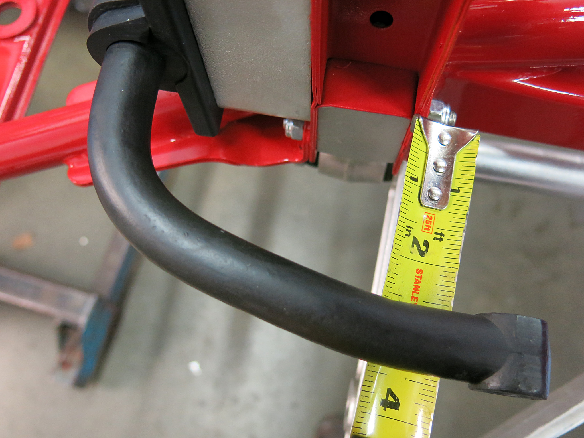
STEP 13 – Adjust the sway bar bushing to be equal on both sides then tighten the two bolts.
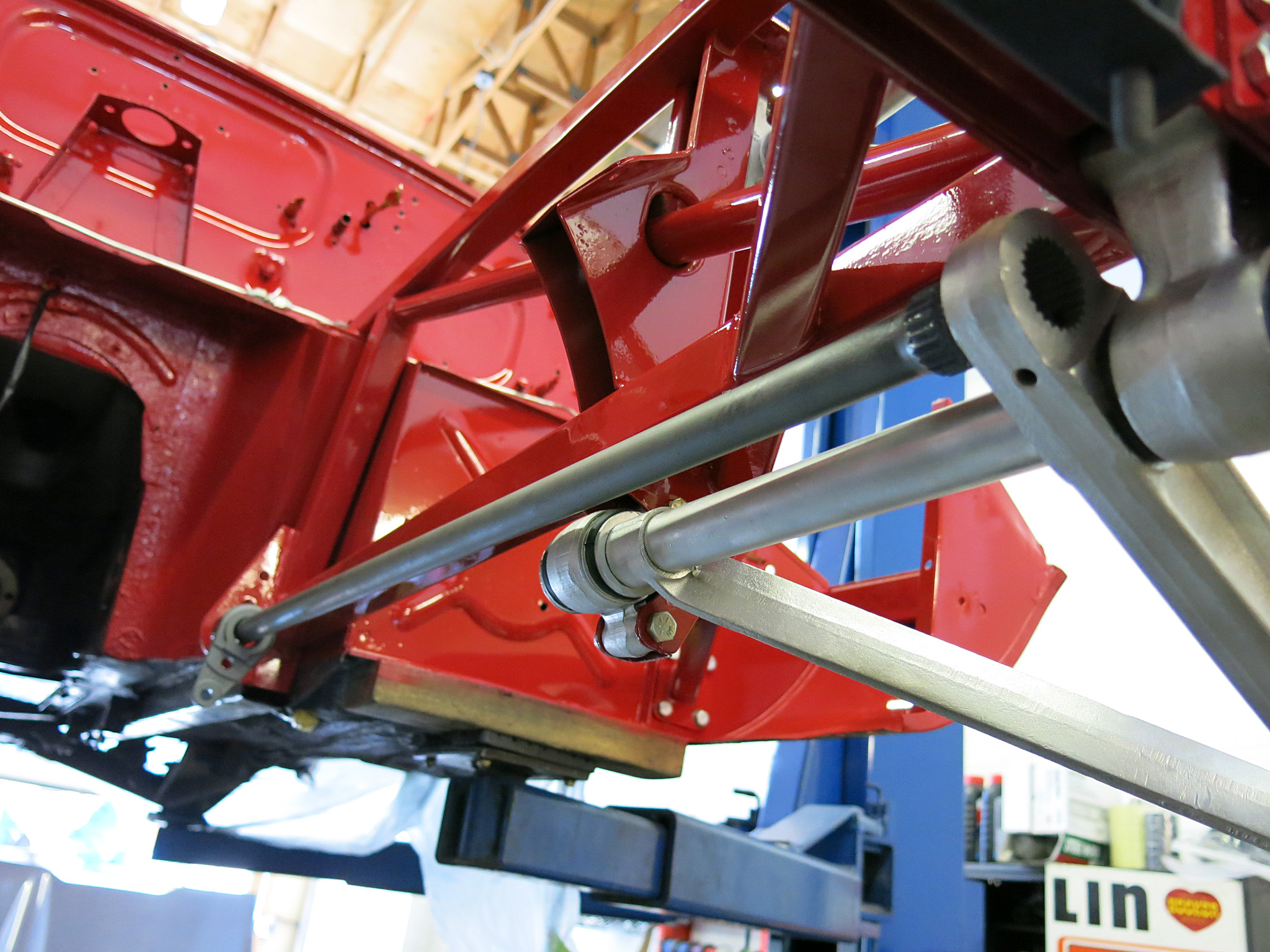
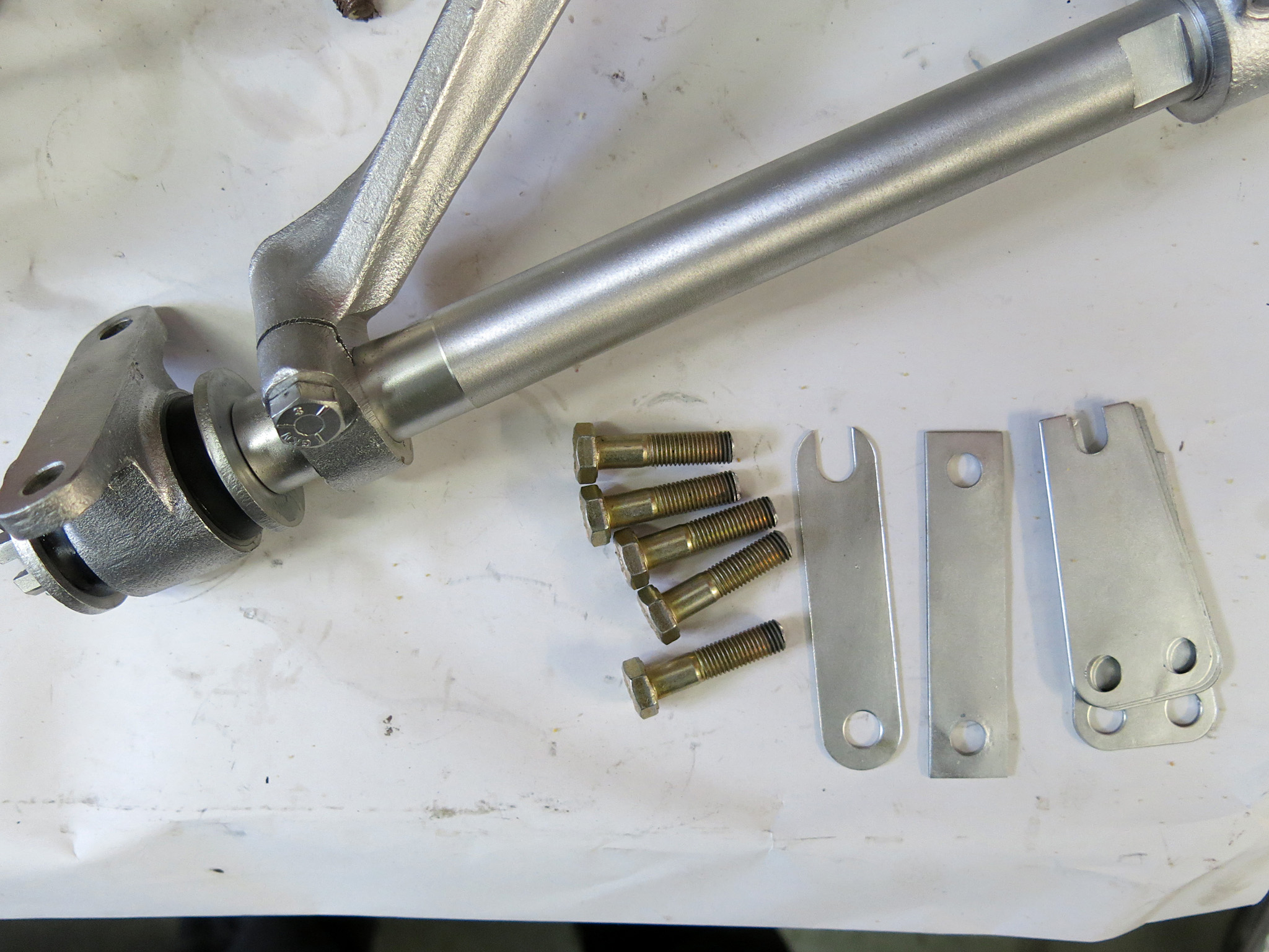
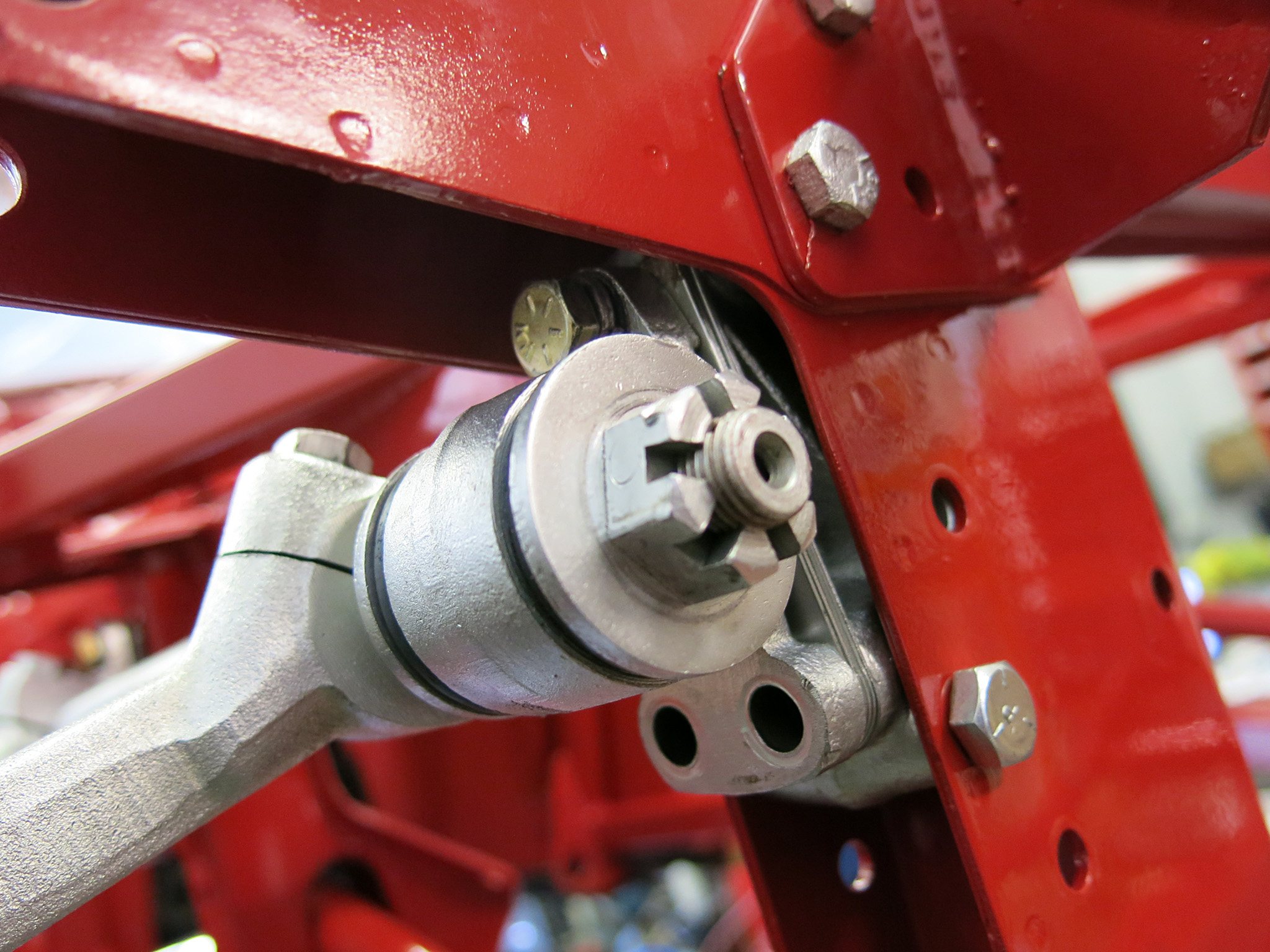
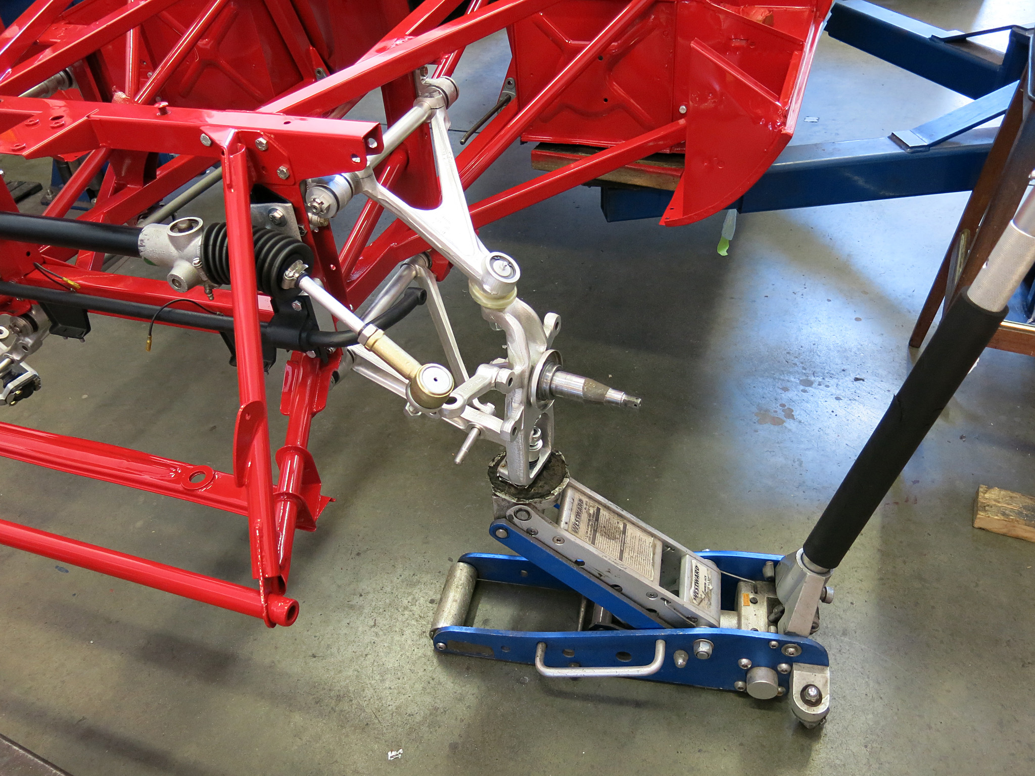
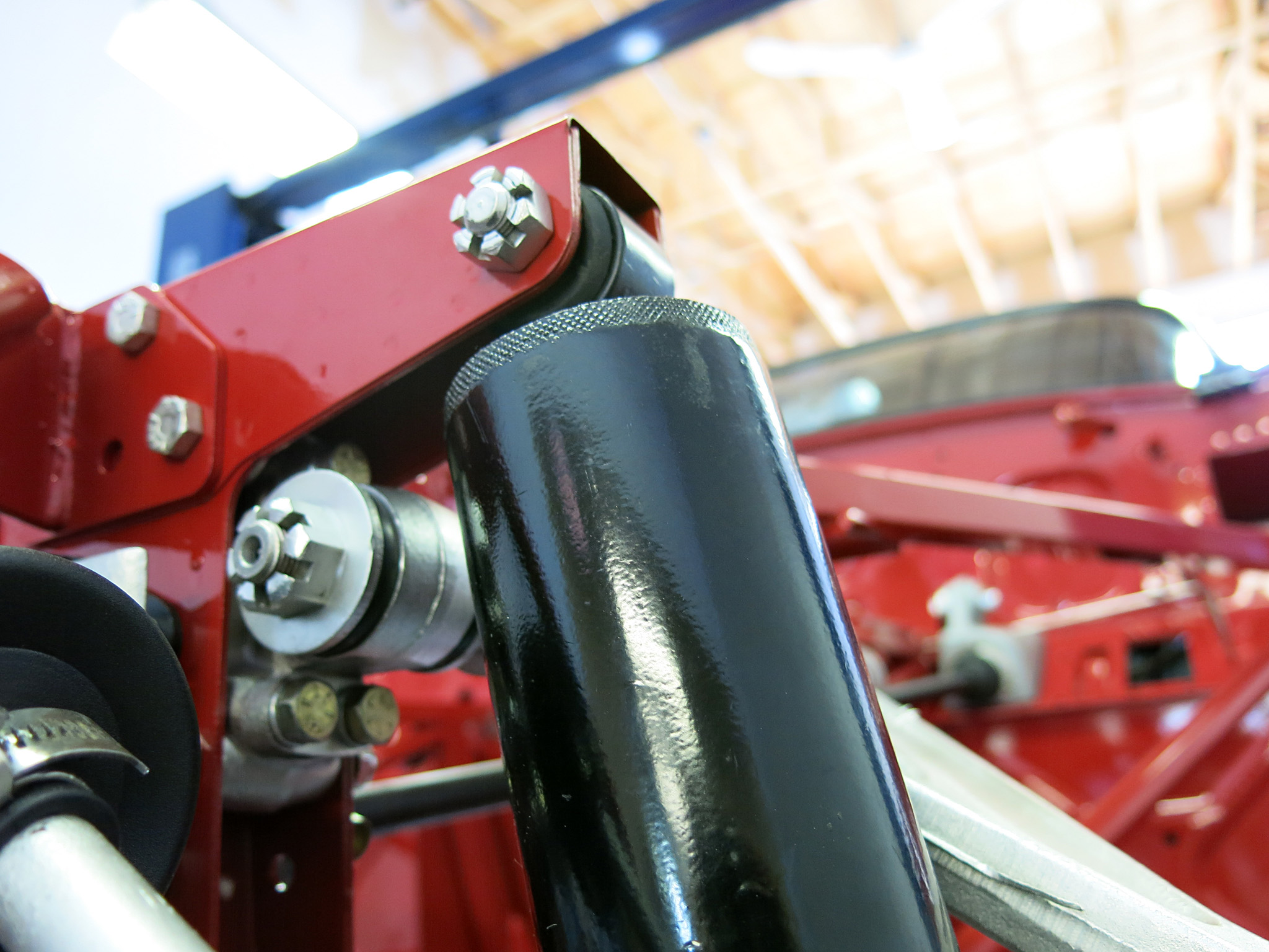
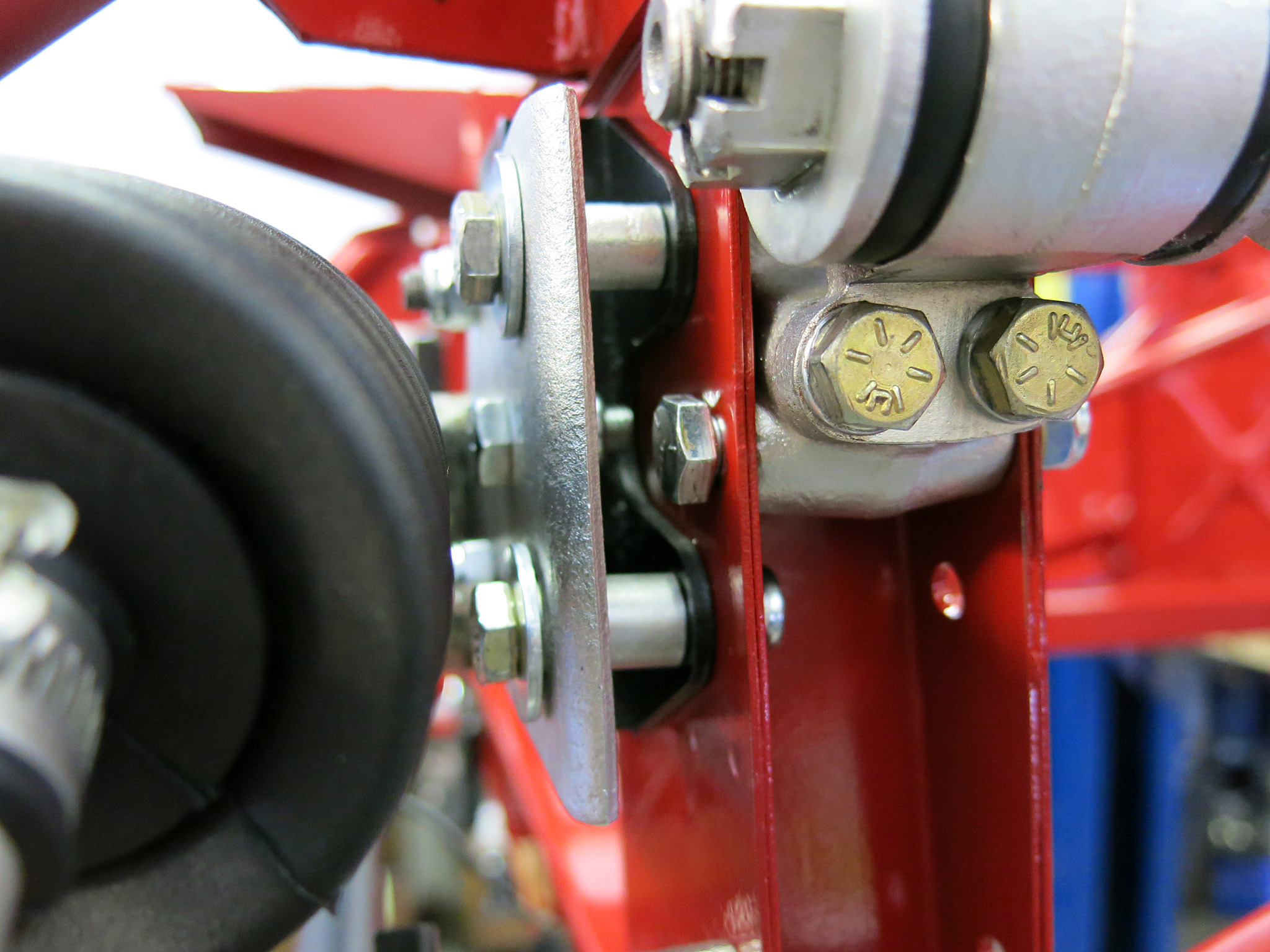
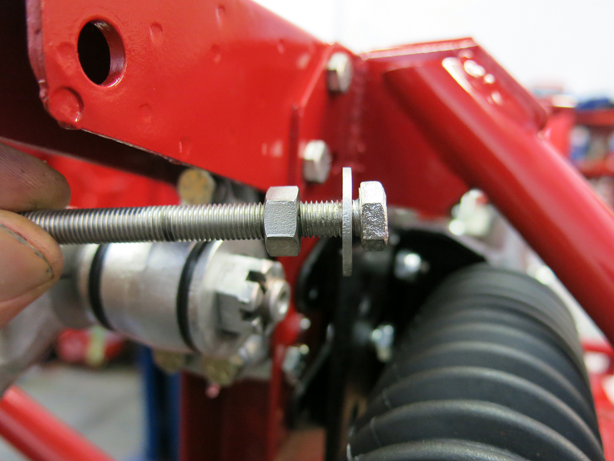
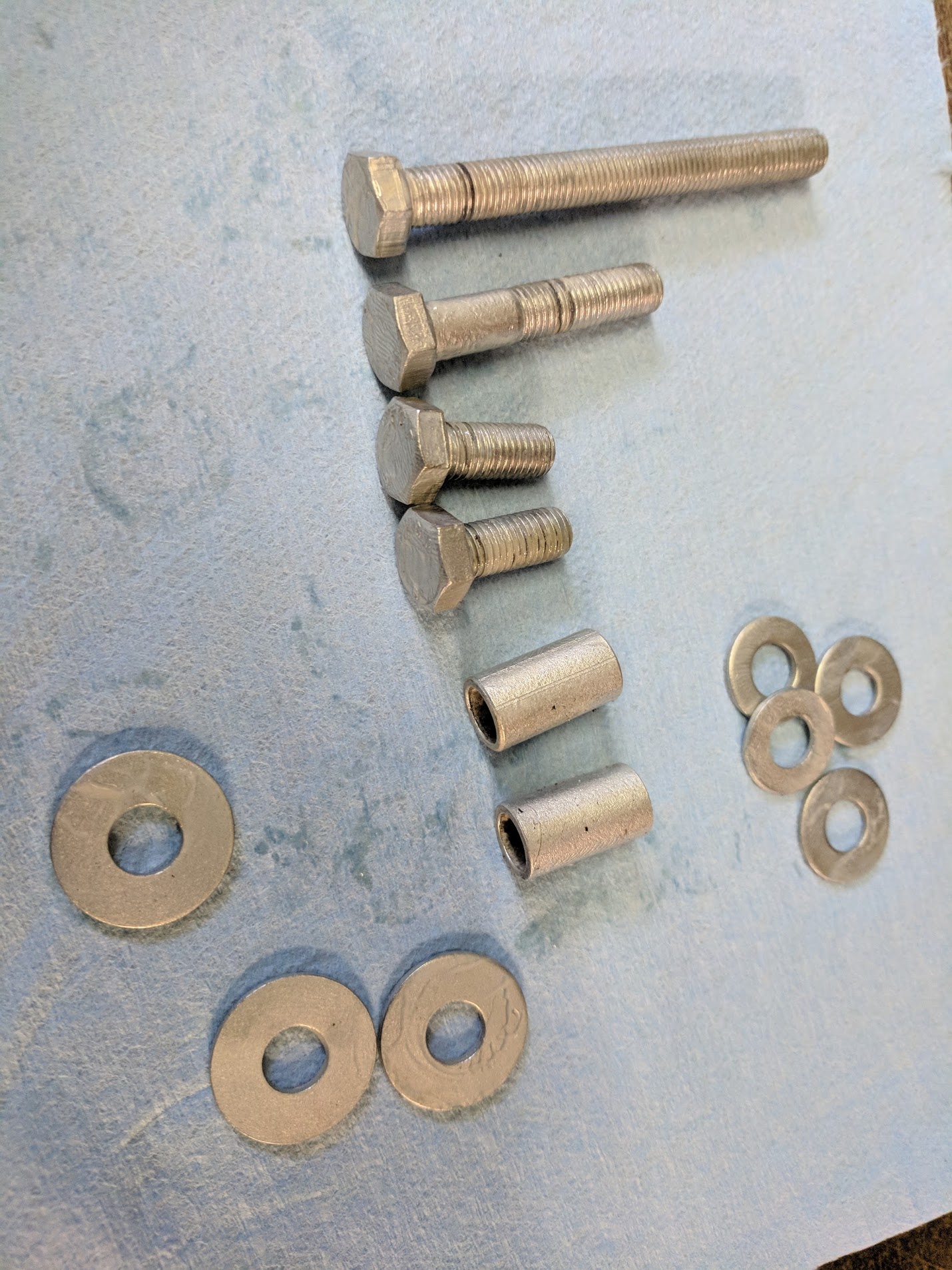
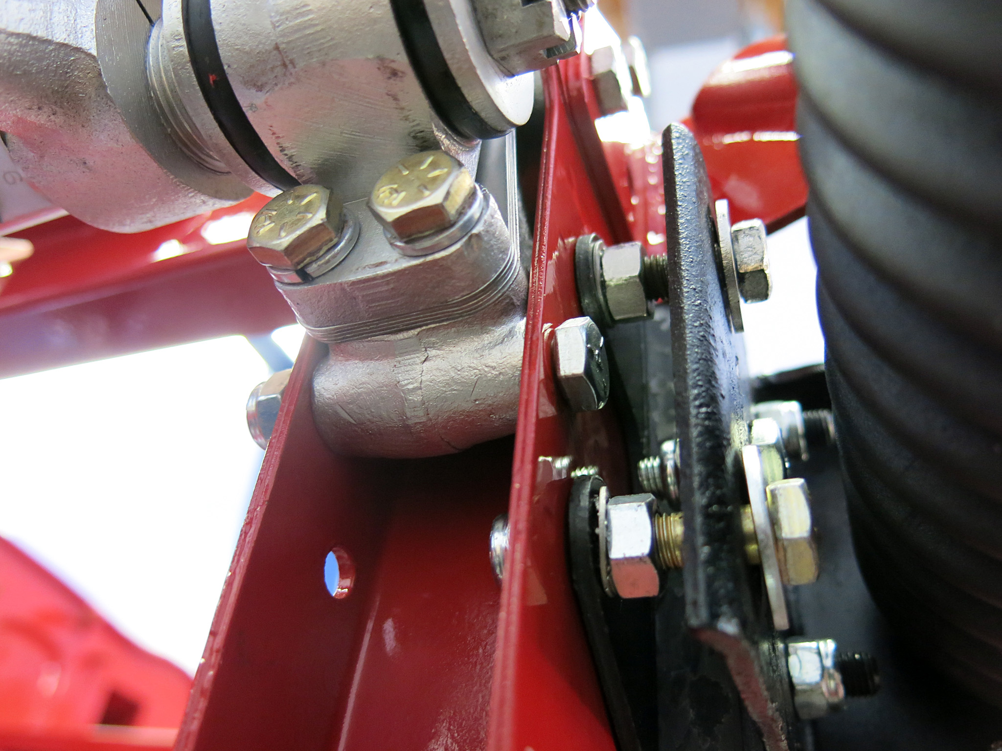
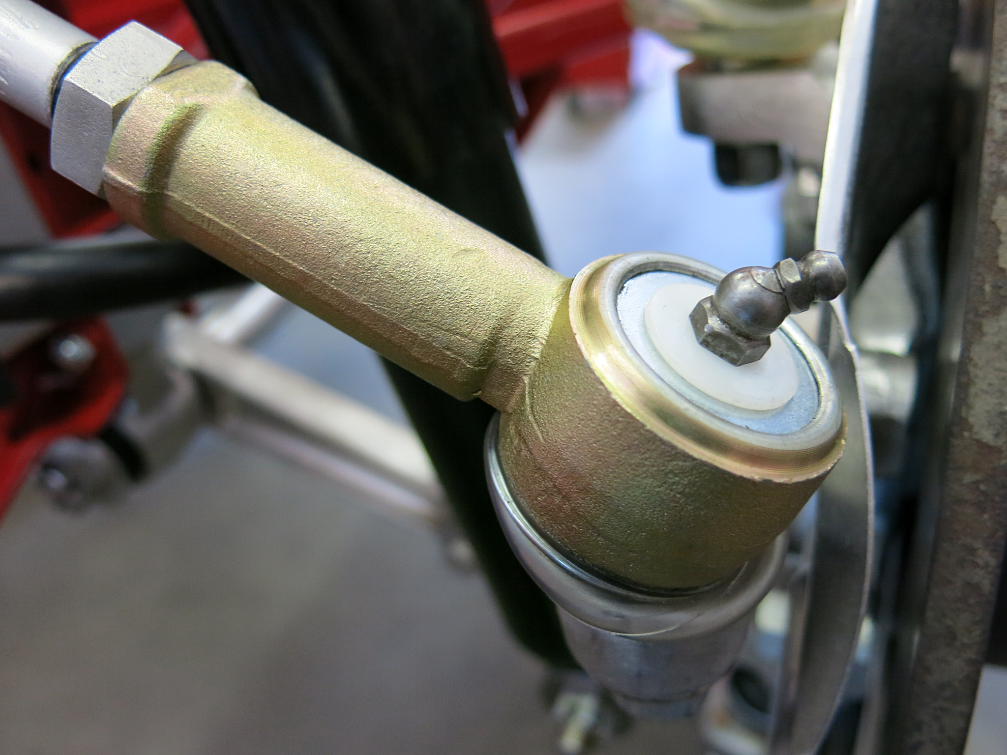
Step 14 – Now we can finally tighten all the bolts. We started with the firewall and worked forward. Our machinists guide recommended 20 ft lbs for new Grade 5 5/16 bolts.STEP 15 – Next prepare the upper control arms. The 13/16 slotted nuts will need to be slightly preloaded to fit in the frame. Also the .030 inch spacers are pictured which were used by the factory to align the top control arm. One of the four bushing retainers on our car had no spacers. When fitting the upper control arm there are shims underneath the upper fulcrums that will adjust the front wheel camber. Many cars from the factory were not fitted with even number of shims because the front fulcrum is actually the camber adjustment, and the rear is less important as it only helps center the fulcrums with the shaft and avoid a preloading the bushings.STEP 16 – Loosely install the control arm with only the top nuts and slide in the shims. The bolts for this are 5/16×1¼ with a small flat section.STEP 17 – Lots of work shown here on the Hub Carrier C20811 or C21256. It was sand blasted then cadmium plated as per original. This stub axle was the original. When fitting a new one please use a grade 8 nyloc and 130 ft lbs. All ball joint tapers need to be pretested for correct seating. Prepare the front spindle by attaching the lower ball joint. Ours has an XJ40 unit which is sealed and need smaller bolts 5/16-3/4 bolts. We still used the paired tab washers. STEP 18 – The next couple steps show linking up the rest of the suspension with the jack pre-loading the torsion bars. Typically I would recommend installing the engine at this point to fit the torsion bar and reaction plate together. So after the engine is installed, attach the stub axle carriers with the provided nyloc nut to the lower and upper control arm. With a jack and the car’s weight you can mate up the top control arm with out spining the ball joint. If the lower taper spins, apply downward pressure with a 36-Inch Handled Pry Bar.STEP 19 – Mount both dampers with the jack still in place. The Tie rod ends are easy to fit at this point at this point, if the ball joint rotates apply downward pressure with a 36-Inch Handled Pry Bar. With the jack removed, the damper has to limit downward movement, not the tie rod ends or anything else. STEP 20 – Install the steering rack bushing to the picture frame using the sole 5/16 nylock nut. If the upper steering column assembly is installed, then the steering column must be in place before the next step.STEP 21 – On the driver’s side install the rack to the rubber bushings, tighten all three bolts between the rack and bushing. Next install the two limiting bolts and washers with spacers that act as a loose safety for the rack and limit the mounting plate movement.STEP 22 – The passenger side is somewhat different to mount and uses two nuts instead of a spacer on the limiting bolts. This unusual 5/16 upper limiting bolt contains no flat.Here is the hardware for the RH steering rack mount. The fully threaded bolt is 5/16×3 while the distance spacers are 3/4STEP 23 – Attach the rack to the rubber bushing then install the double-nut limiting bolts that will limit the rack movement.STEP 24 – With the jack again preloading the torsion bar, screw on the tie rod ends to the steering rack and then seat them into the stub axle carrier. TOP TIP: remove the grease nipple and attach it after lowering the suspension to rest position. If they bottom out then some material will have to be taken off the threads. Some tierod ends do not allow sufficient droop to let the telescopic shock absorber hold the torsion bar tension.
STEP 25 – Mount up the sway bar with the links that extend down to the lower control arm.
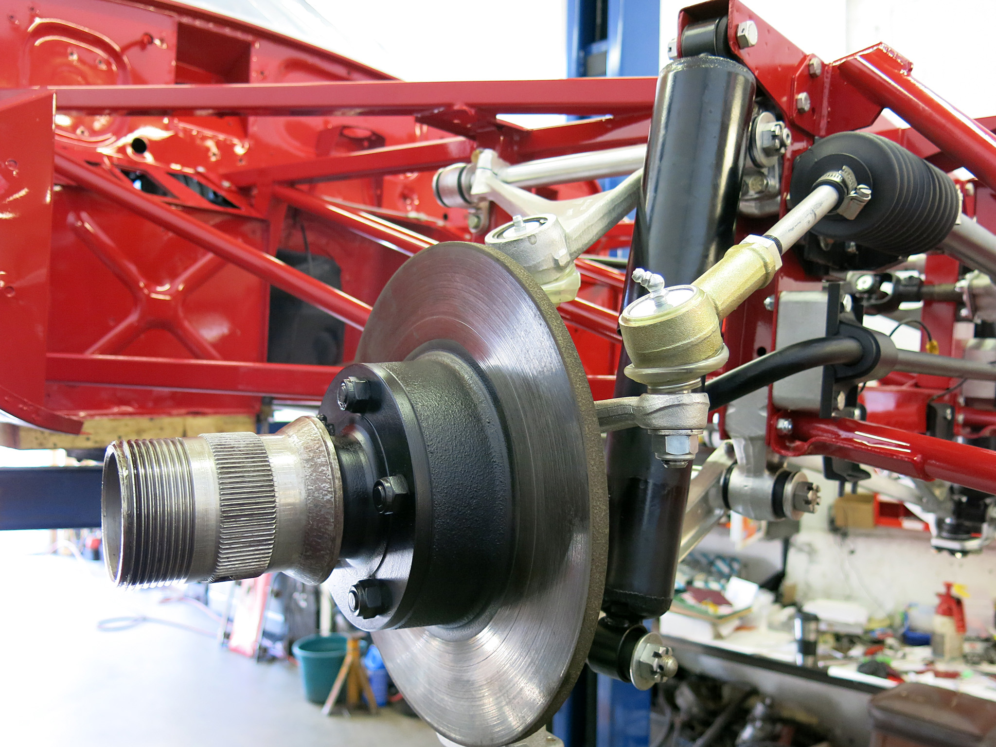
STEP 26 – Install the Front hub and rotor to the axle stub with the oil seal, inner bearing packed with grease, outter bearing packed with grease, D-Washer and slotted nut. The correct tension is listed in the service manual and the wheel bearings should not be locked tight.
Ok well that wraps up this guide to installing the E-Type engine subframes. If you have any comments/corrections or thoughts please include them in the comments section.
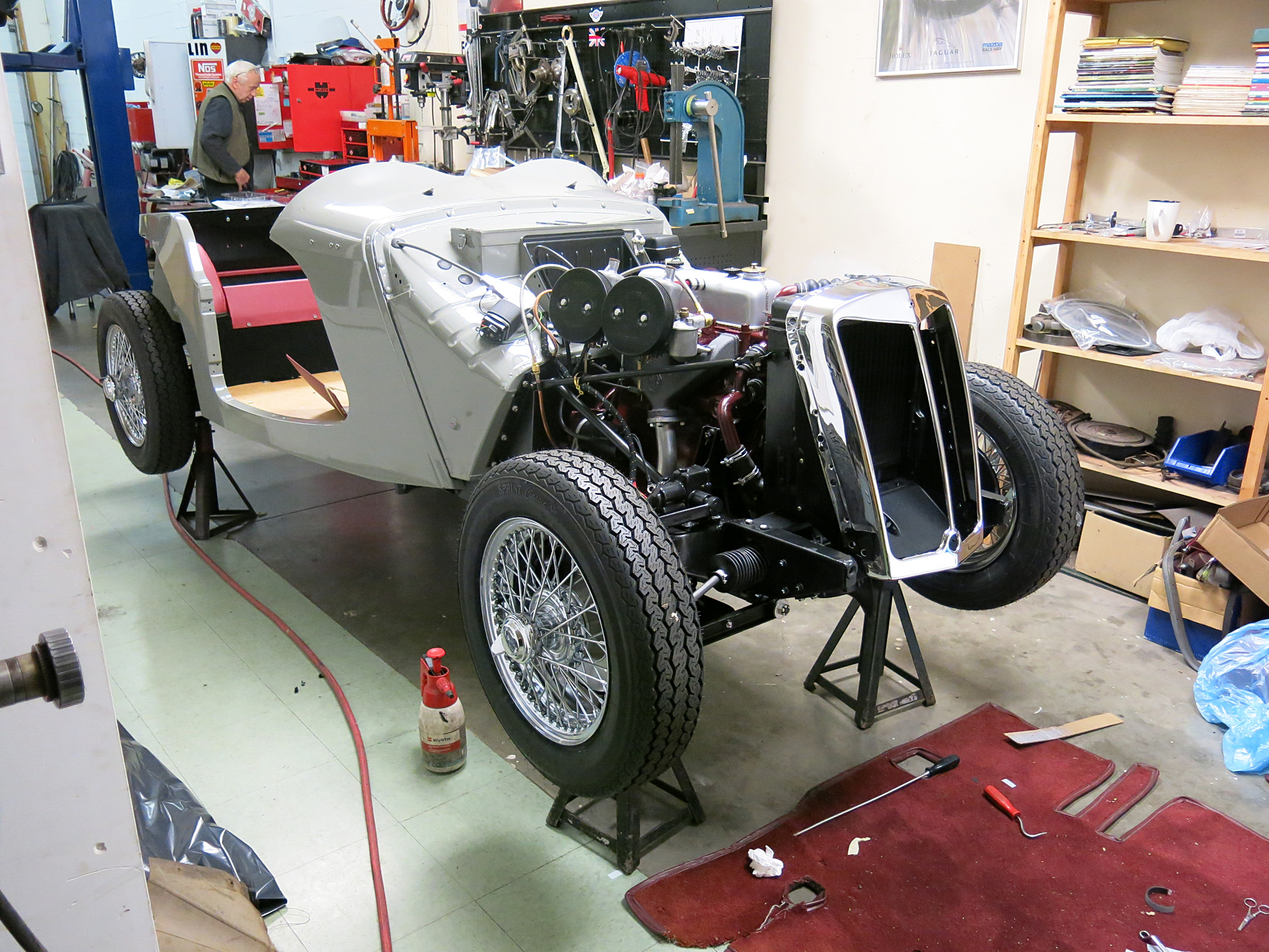
We have finally finished our 1965 E-Type engine bay restoration. The project is back with the owner for some detailing and then we will have the distinct pleasure to offer this car on the market.